|
SERWIS ELEKTRONICZNY - RADIOELEKTRYKA SOSNOWIEC POLSKA |
|
NIEZALEŻNA DZIAŁALNOŚĆ BADAWCZO - NAUKOWA KLIKNIJ NA OPIS DOKUMENTU |
|
|
|
|
|
MSA1105TR1 17dB 500mW POBIERZ PDF MSA 1105 (201 KB) 1uHz (Microhertz) =
1000nHz (Nanohertz) = 10-3mHz
(Milihertz) |
Zasięg nadajnika
radiowego fm: Prędkość fali elektro-magnetycznej w próżni: 300000 km/s (kilometr na sekundę) Prędkość światła w próżni: 299792458 m/s (metr na sekundę) Wzór: (300 x 106
m/s) / częstotliwość (Hz=1/s) (herc).
Czytaj więcej... |
|
|
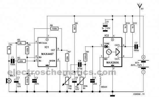
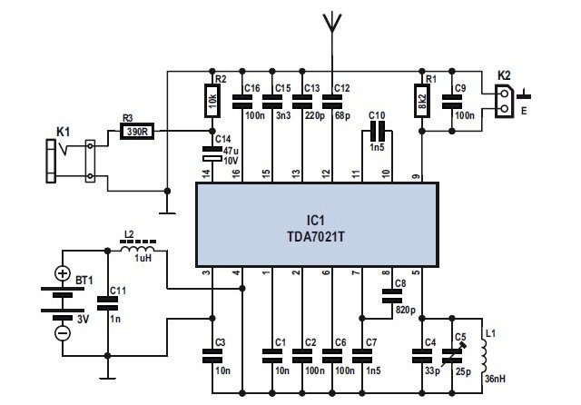
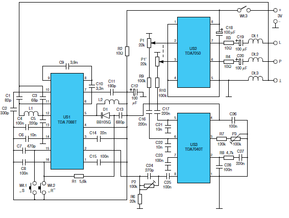
| Obieg w Figurze 1 może retransmitować dźwiękowy sygnał od ośrodka telefon do mownego diapazonu FM. Kiedy użytkownik rozmieszcza ośrodek telefoniczny spiker koło mikrofonu, on czy ona może przysłuchać się komórkowy telefoniczny dźwięk przez FM radio pojazdu. To może być wykorzystane, jak samochodowy dla wejścia bezpłatny dla rąk mikrofon z głośnikiem.IC1 - integralny kontrolowany przez napięcie oscillator IF (Vco) z dyferencjalną produkcją, która podtrzymuje 70mhz do 150mhz szeregu częstotliwości, który pokrywa całą grupę radia FM. |
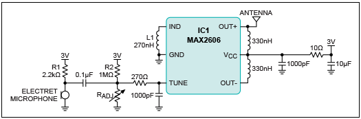 Liczba 1. Obwód FM nadajnika z mikrofonem do użytku jako telefon komórkowy umożliwiający pracę bez użycia rąk. Mikrofon bezprzewodowy 696 mW -10 dBm. PDF 3296 POBIERZ (196 KB) PDF 3006 POBIERZ (182 KB) Dławik 0,33uHz (Microhertz) = 3,3mHz (Milihertz), 0,27uHz (Microhertz) = 2,7mHz (Milihertz). |
| Induktor L1 ustala Vco center szereg nastrajania. Wybierzcie L1 takie, że efektywny induktywizm od szpilki Ind do GND przyprowadza output częstotliwość 100mhz.Ta częstotliwość koresponduje z centrum grupy FM. Induktor znaczenie 270nh pokrywa nastrajanie 97mhz do 128mhz szeregu. Potem, regulujcie rezystor Radjo dla nastrajania Vco do specyficznej częstotliwości stacji FM. Rezystory R2 i Radj skłaniają wewnętrzny varactor. Stacje FM znajdują się na przedziałach 0.2 MHz przerwy. |
Liczba 2.
Obwód FM
nadajnika z bezpośrednim wkładem audio eliminuje szum tła z
mikrofonu
.Transmitter CD 696 mW -10 dBm POBIERZ PDF MAX2605-2609 (318 KB) |
|
VCO potrafi ze zróżnicowanej mocy wyjściowej z do -8 dBm. Na mikrofon elektretowy wpływają z R1. AC-łączyć/połączyć mikrofon sygnał dźwiękowy moduluje Częstotliwość VCO przez zmienianie V TUNE. częstotliwość VCO wyjściowa będzie przestrzegać pojemności albo amplituda z mikrofonu. Sygnał dźwiękowy z około 20 mV RMS jest odpowiednie dla funkcjonalność. Nie górny-modulujcie Vco, czy resulting dźwięk od odbiorcy FM będzie wykrzywione. Górny-modulując Vco również osłabia carrier sygnał, wypuszczając potęgę na niewykorzystanym spektrum odbiorcą. W Figurze 2, mikrofon i R1 zamieniają się z prostym podłączaniem dźwiękowy port wyprowadzenia komórkowego telefonu. Objętości komórkowego telefonu należy być skorygowany odpowiednio dla optymalne wykonanie. Proste podłączanie do komórkowego telefonu wyłączy tło szum mikrofon.MAX2606 45mhz do 650mhz, Zjednoczył IF Vcos z Dyferencjałem Output. KODY PASKOWE REZYSTORÓW I DŁAWIKÓW |
|
|
 |
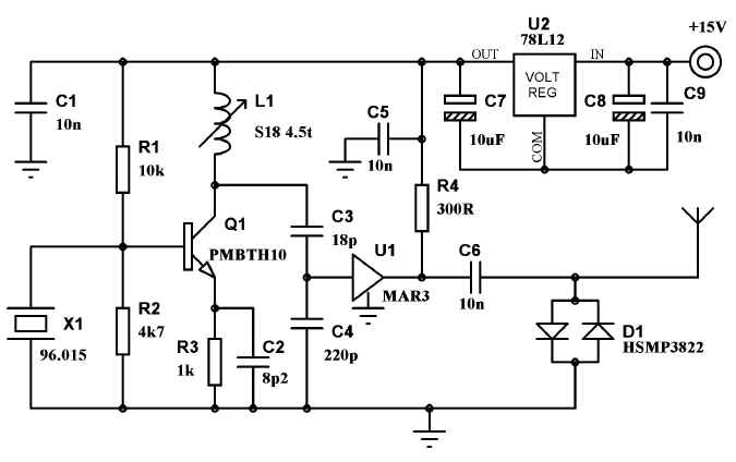
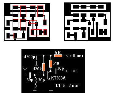
Home / Radio / DIY Crystal Oscillator Circuit crystal
quartz oscillator circuit diagram A very simple DIY crystal oscillator circuit which use a quartz for frequency stability and a good rf transistor. Use a 2-nd or 3-rd harmonic crystal, for example if you want 100MHz use a 50MHz or 33.3 MHz quartz or if you want use a 4-th harmonic crystal but the output rf voltage will be lower. The L coil has 5 turns 0.8mm Ø, 6mm Ø, 1 mm step, output at first turn from voltage plus. Use C4 for fine frequency adjustments. For a great frequency stability, this crystal oscillator circuit must use a good varicap diode (you can use BB139) and a good crystal too. Related Products: Oscillators and Crystals | Crystals | SMD Crystal Oscillator | TH Crystal Oscillator DIY crystal oscillator circuit components
|
|
|
 |
 |
|
|
|
|
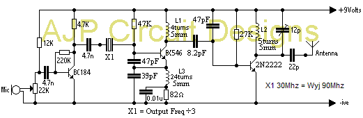
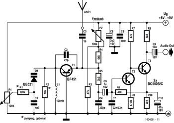
Ten prosty FM mikrofon bezprzewodowy nadajnika może transmitować mowę nad krótki zasięg. Można go używać jako prosty cordless mikrofon. Obwód używa dwóch integrujących - obwodów od maxim. IC1 MAX4467, są amplifikatorem podnoszą sygnał mikrofonu poziom stosowny dla częstotliwości modulacji. IC2 są kontrolującym oscylatorem z zintegrowanym varactor (a.k.a varicap dioda). On jest taki mały że może znaleść zastosowanie w bezprzewodowym mikrofonie reporterskim. Bezprzewodowy mikrofon zapewnia oscylację częstotliwości około 100 MHz. Dla niego najlepszy sygnał, L1 musi być wysokości składnikiem. nominalna częstotliwość oscylacja ustawia induktor l1. Ten induktor ma wartość 390 nH L1 może składać się 4 zwoji o średnicy 10 mm. Cewkę rozciągnoć na długość około 1,5 cm. |
|
Średnica drutu może
być czymś między 26 SWG (0.5 mm) i 20 SWG (1 mm). Żaden rdzeń nie
jest używany. |
|
|
|
|
|
|

|
|
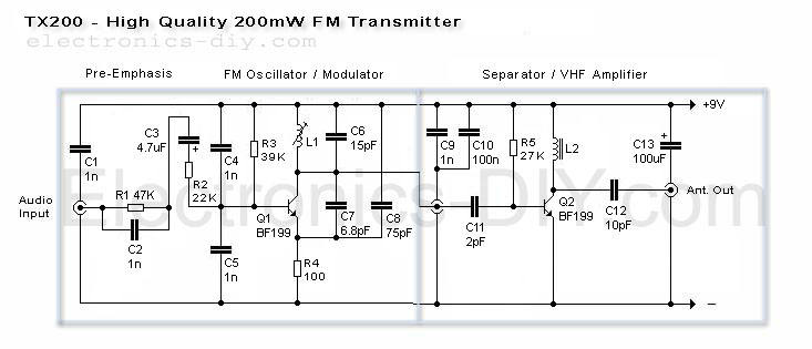
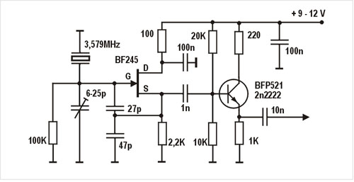
Ten nadajnik FM UKF będzie wyjście około 250mW mocy
RF za pomocą tranzystora wyjściowego 2N3866 i może pracować między
75MHz i 146MHz . narzędzia on zmienny o wysokim wzmocnieniu dźwięku
przedwzmacniacza , który może wykryć głosy 40 stóp od korzystania z
mikrofonu elektretowego . Za pomocą skanera NBFM, przebiega 5KM
zostały osiągnięte
4 obroty na 85MHz do 100MHz i 3 włącza do 100 do 146MHz . Dla częstotliwości powyżej 100 MHz Crystal będzie większe niż 20 MHz tym samym podstawa emiter kondensator powinna być 47pF . L3 jest dławik 4.7uH . Jest to idealne miejsce , aby dostroić się tym obiegu za pomocą miernika fali detektora umieszczone kilka cali od nadajnika. |
Transmitter 250 mW stabilizowany rezonatorem kwarcowym. Sprawdzony zasięg w terenie zabudowanym (pomieszczenie ekranowane) antena 10cm, zasięg bez szumów 25 metrów. Dławik 4700nh. PDF BC547 POBIERZ (191 KB) PDF CERAMIC TRIMMER POBIERZ (633 KB) |
|
|
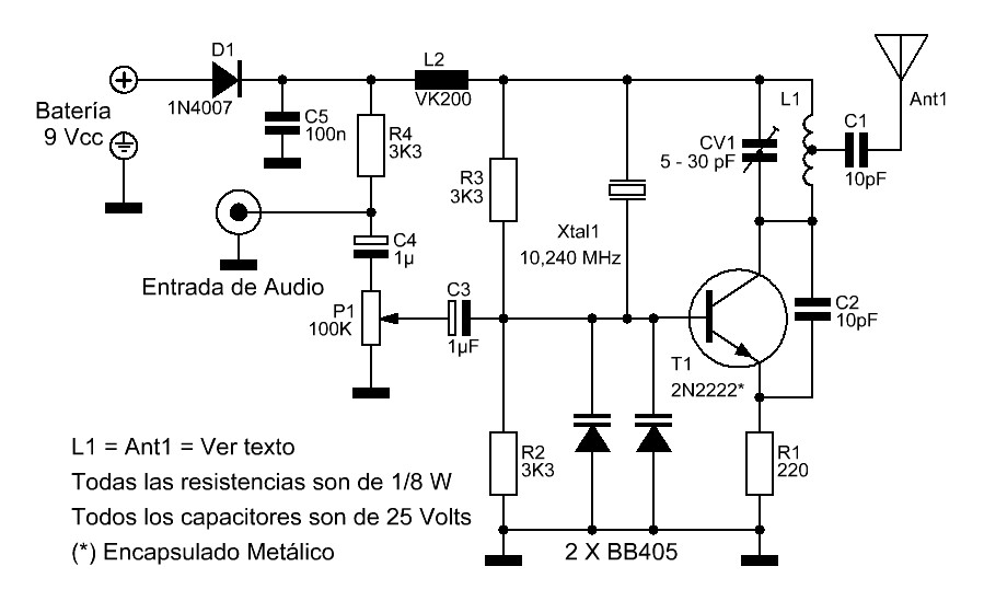
 Transmitter 88-104 Mhz. Zasięg 20 - 50 metrów. Fm. PDF BC547 POBIERZ (191 KB) PDF 2N2222 POBIERZ (107 KB) |
Wzmacniacz wysokiej czenstotliwości - 0,6W. |
|
|
|
22SWG = Średnica w mm : mm 0.711 mm Średnica w calach : w 0.028 in Powierzchnia przekroju w milimetrach kwadratowych : 0.3973 mm2 |
|
|
|
|
|
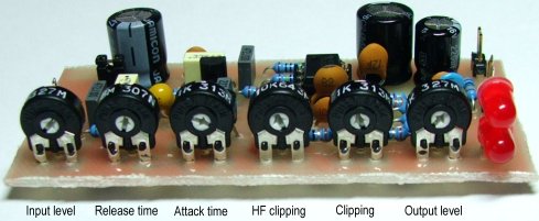
 Inteligentny przedwzmacniacz PDF AVT 2312 POBIERZ (1,07 MB) |
Opisany dalej układ doskonale współ−pracuje z mikrofonem elektretowym, ale bez przeróbek może też współpracować z innymi źródłami sygnału. Może więc pełnić funkcję uniwersalnego niskoszumnego przedwzmacniacza mikrofonowego z auto−matyką. W tej roli znajdzie zastosowanie we wszelkich systemach nagłośnienia, w układach telekomunikacyjnych i radioko−munikacyjnych, telekonferencyjnych, w dy−skotekach, systemach rozgłaszania (np. dworce PKP i PKS), itp. Będzie też znako−mitą pomocą przy wszelkich nagraniach, pełniąc rolę skutecznego ogranicznika, nie dopuszczającego do przesterowania toru zapisu. Szczególne właściwości układu u−możliwiają wykorzystanie go jako gitarowe−go efektu wybrzmiewania (sustain) o bar−dzo dobrej jakości. |
|
|
|
Specyfikacja Moc: Prosty nadajnik radiowy 400 mW.
Zasilanie nadajnika: 12-14 V Częstotliwość pracy: 87,5-108 MHz
stabilizowany. Pobór prądu: 100 mA. RF moc: 400 mW. Impedancja:
50-75 ohm. Modulacja: FM szerokopasmowa.
Czytaj dalej... L1 30nH (0,03uH) L2 60nH (0,06uH) L3 30nH (0,03uH) POBIERZ PDF BFR96 (117 KB) POBIERZ PDF BB112 (74,7 KB) POBIERZ PDF BB409 (59,5 KB) POBIERZ PDF BB105 (1,24 MB) POBIERZ PDF BB204 (33,9 KB) PDF BB145 POBIERZ (140 KB) PDF 3296 POBIERZ (196 KB) PDF 3006 POBIERZ (182 KB) PDF CERAMIC TRIMMER POBIERZ (633 KB) PDF BB105B POBIERZ (178 KB) PDF BFR91A POBIERZ (139 KB) |
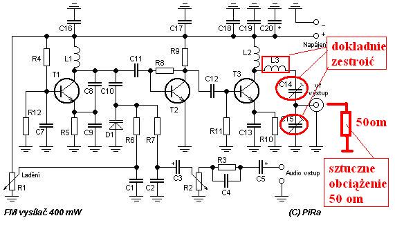 Vf výkon: 400 mW. Frekvence: 87,5-108 MHz. Modulace: FM širokopásmová. |
|
|
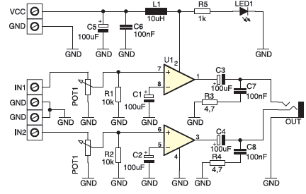
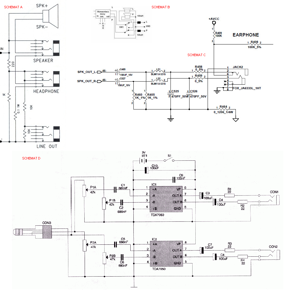
 Miniaturowy wzmacniacz stereo z układem TDA2822M PDF TDA2822M POBIERZ (74,4 KB) |
Miniaturowy wzmacniacz stereo z układem TDA2822M DUAL LOW VOLTAGE POWER AMPLIFIER DESCRIPTION The UTC TDA2822M is a monolithic integrated audio amplifier in a 8-Pin plastic dual in line package. It is designed for portable cassette players and radios. FEATURES *Wide operating supply voltage:Vcc=1.8V- 12V. *Low crossover distortion. *Low quiescent circuit current. *Bridge/stereo configuration. |
|
|
|
Miniaturowy wzmacniacz mono z układem TDA2822M Wzmacniacz charakteryzuje się minimalną ilością elementów zewnętrzych. Nie wymaga żadnego strojenia ani regulacji. Pracuje od razu po prawidłowym zmontowaniu. Może mieć zastosowanie jako dodatkowy wzmacniacz do walkmana, do samodzielnie konstruowanych odbiorników radiowych, pozytywek. Ze względu na niewielkie wymiary płytki może być również zastosowany w miejse trudno dostępnych układów w sprzęcie RTV. Niewielki pobór prądu umożliwia zasilanie układu z baterii. |
 Miniaturowy wzmacniacz mono z układem TDA2822M PDF J-245 POBIERZ (1,10 MB) |
|
|
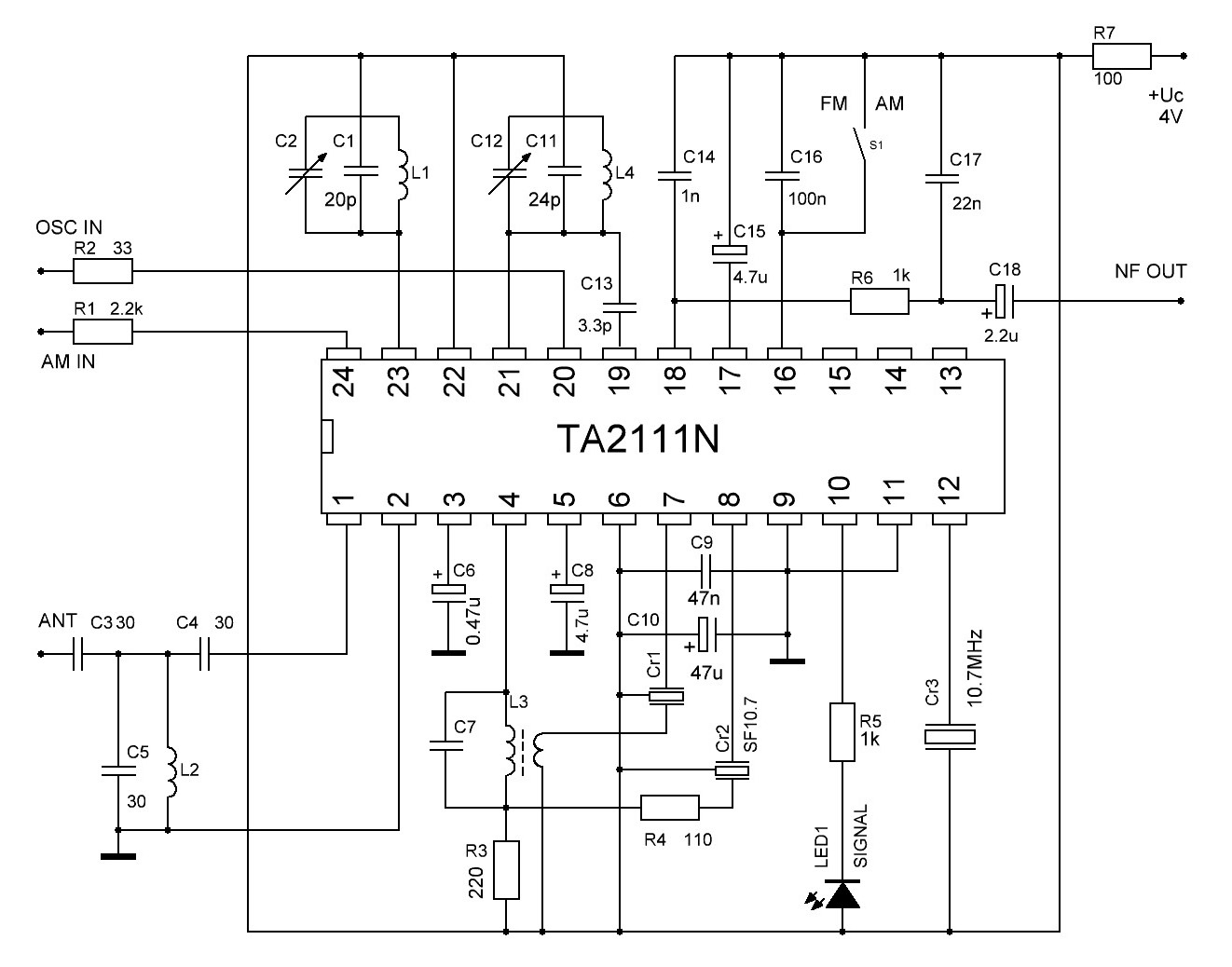 PDF TA2111N POBIERZ (597 KB) |
Радиоприемници, базирани върху шаси от "Геолог" Част IV: FM/AM приемник с ИС TA2111N Интегралната схема на TOSHIBA TA2111N е изключително подходяща за изработване на радиоприемници със задоволително качество и малък брой елементи, което е моята цел в тази серия от конструктивни решения. Естествено има и други такива интегрални схеми като TA8164P, TA8132 и т.н. Трябва да подчертая, че със сигурност разработените радиоприемници са далеч с по-добри характеристики от оригиналния радиоприемник, дори само с факта, че добавяме съвременен УКВ обхват 87-108 MHz. Интегралната схема TA2111N позволява цялостно решение на радиоприемник за АМ и УКВ. В моите схеми стереодекодера е изключен, тъй като шасито на ГЕОЛОГ не позволява тази хубава възможност. Но тъй като аз публикувам оригиналите на печатните платки, естествено всеки може да си ги модифицира и да го добави. Czytaj dalej... |
|
|
|
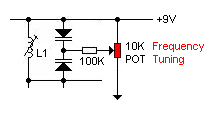
long range fm transmitter This is very stable, harmonic free, long range fm transmitter circuit which can be used for fm frequencies between 88 and 108 MHz. This can cover 5km range (long distance). It has a very stable oscillator because you use LM7809 stabilizer which is a 9V stabilized power supply for T1 transistor and for frequency adjustment that can be achieved by using the 10K linear potentiometer. The output power of this long range rf transmitter is around 1W but can be higher if you use transistors like KT920A, BLX65, BLY81, 2N3553, 2SC1970, 2SC1971… Czytaj dalej... |
Fm transmitters PDF 199 PHILIPS POBIERZ (49,1 KB) PDF BF199 POBIERZ (144 KB) PDF 3296 POBIERZ (196 KB) PDF 3006 POBIERZ (182 KB) PDF CERAMIC TRIMMER POBIERZ (633 KB) |
|
|
|
fm transmitter circuit schematic PDF BF982 POBIERZ (128 KB) |
The most important part of this 88-108 transmitter is
the Colpitts oscillator. C3,C4,C5,C6,CD1-CD2 ans L1 determine the
transmission frequency. The RF Oscillator
circuit has the BF982 MosFet transistor wich is the active part. The
others 2 transistors separate the VCO from antenna. FM transmitter circuit diagram The first stage BF199 amplifies the weak signal from the vco and functions in constant load. The second stage BFR90 amplifies the rf signal to load the antenna wich will radiate the radio frequency power. Antenna can be one wire, 70 cm long. L1 coil has 1mm thick copper wire, 3.5 turns, 5 mm diameter and 1mm space between turns. You can use BF199 instead of BFR90 and MV104 instead of the 2 varicape diodes. Czytaj dalej... |
|
|
|
Pira CZ 5W PLL FM Transmitter Easy to build high-quality PLL FM transmitter with typical output power of 5 W and no-tune design. The transmitter includes RDS/SCA input and Audio/MPX input with optional preemphasis. It can be used with or without stereo encoder. Tuning over the FM band is provided by two buttons that control dual-speed PLL. The transmitter can work also without the LCD display. Some experience with building devices of this kind are highly recommended. Characteristics Supply voltage 11-13.8 V (stabilised or from a battery) Supply current up to 1.2 A Standard frequency range 87.5-107.9 MHz Audio/MPX input sensitivity 2 V pp (for 75 kHz freq. deviation) RDS/SCA input sensitivity 0.2 V pp (for 7.5 kHz freq. deviation) Board dimensions 109 x 54 mm Czytaj dalej... |
 Transmitter 5W |
|
|
 PDF 3296 POBIERZ (196 KB) PDF 3006 POBIERZ (182 KB) PDF CERAMIC TRIMMER POBIERZ (633 KB) |
Transmitter w.cz 87-107 MHz Then you can connect antenna and audio signal. Adjust R1 until the audio sounds as loud as the other stations, With a good antenna (dipole placed outdoor and high) the transmitter has very good coverage range about 1500 meters, the maximal coverage range is up to 20 km. |
|
|
|
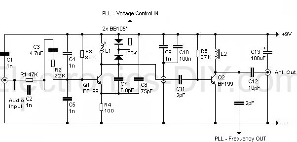
Schemat generatora z separatorami. |
 Płytka drukowana GIF (6,21 KB) PDF 3296 POBIERZ (196 KB) PDF 3006 POBIERZ (182 KB) |
|
|
 PDF CERAMIC TRIMMER POBIERZ (633 KB) |
Schemat stopni mocy nadajnika fm. |
|
|
| Transmitter FM. Wykaz elementów PNG (38,6 KB) |
PDF CERAMIC TRIMMER POBIERZ (633 KB) |
|
|
|
|
Transmitter stabilizowany rezonatorem kwarcowym 49 MHz. Wykaz elementów PNG (27,8 KB)
|
|
|
|
|
|
|
 |
|
|
|
|
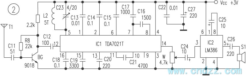
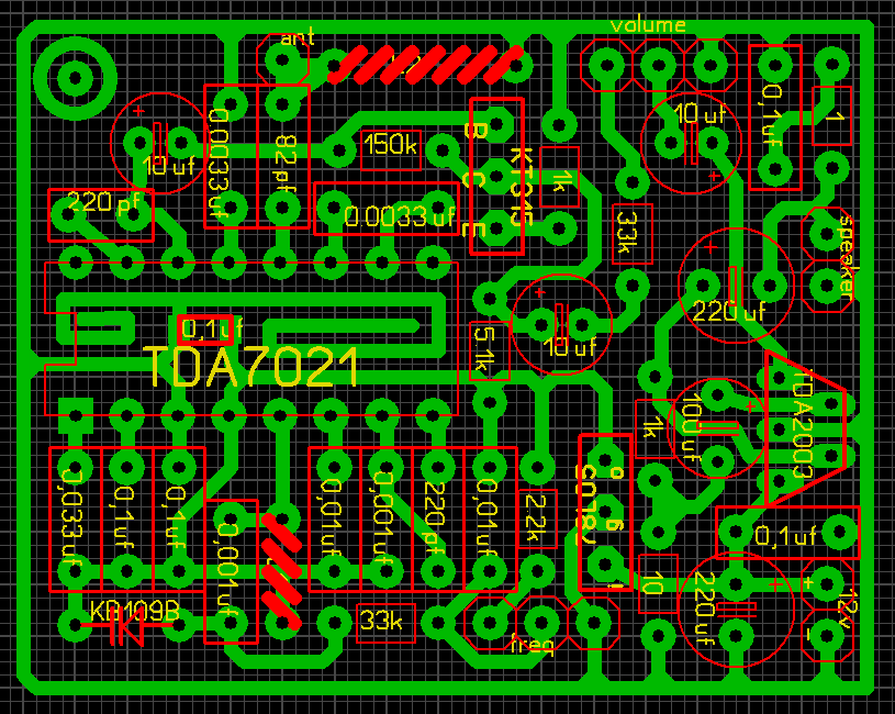
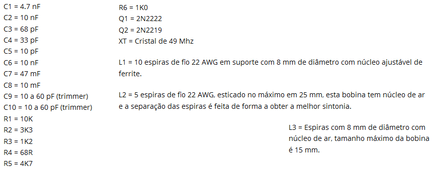
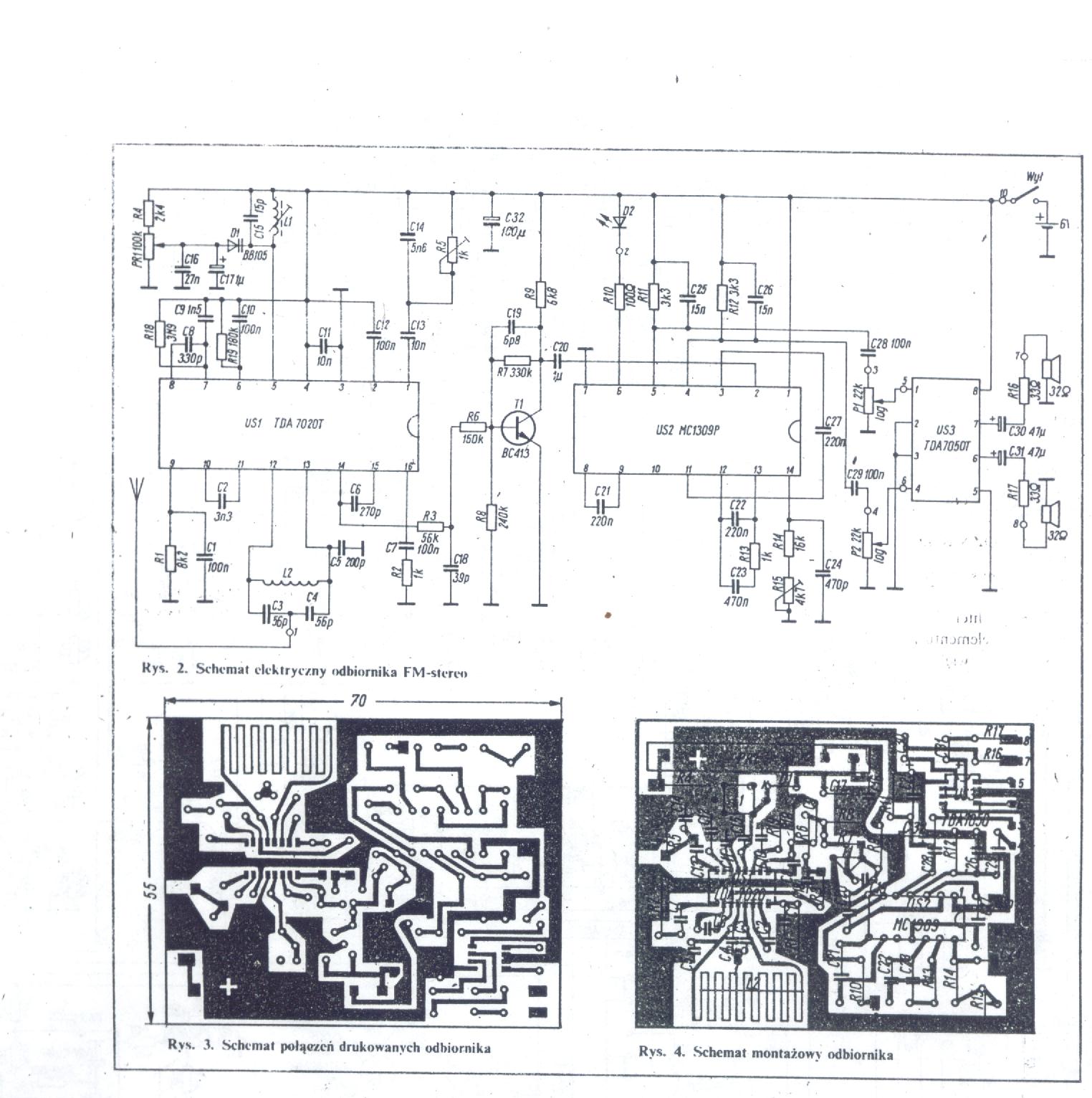
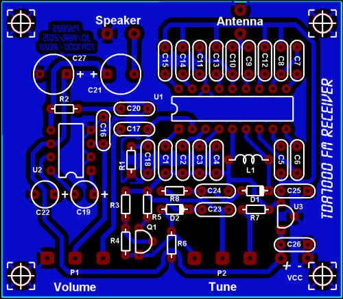
Odbiornik radiowy UKF na pasmo 66-110Mhz Odbiornik przeznaczony jest do odbioru audycji nadawanych w paśmie 88-108 Mhz. Zbudowany jest na układzie TDA7020 (TDA7021). Układ ten zawiera w swojej strukturze wszystkie tory odbiornika FM: wzmacniacz w.cz., heterodynę, mieszacz, wzmacniacz p.cz, demodulator i układ wyciszania. Odbiornik ten cechuje brak elementów indukcyjnych w torze p.cz., co osiągnięto dzięki zmniejszeniu częstotliwości pośredniej do 76kHz. Podstawowe parametry układu TDA7020: - napięcie zasilania 1,8-V - stosunek sygnału do szumu 60dB - prąd zasilania 6mA - czułość przy S/N -26dB - zakres ARCz 160kHz L1 najwygodniej nawinąć na wiertle o średnicy 5 mm. Należy nawinąć 5 zwojów drutu o grubości 0,7 mm. (20nH) Cewkę L2 obwodu heterodyny nawinięto na korpusie z filtru 7 x 7. Uzwojenie ma 4 zwoje drutu CuAg fi 0,8. (36nH) (filtr nr216) |
 TDA7020 MC1309P STEREO PDF 3296 POBIERZ (196 KB) POBIERZ PDF BB105 (1,24 MB) PDF J081 POBIERZ (291 KB) PDF 78L05ACZ POBIERZ (66,8 KB) PDF 78L05 POBIERZ (980 KB) PDF TDA7021 POBIERZ (145 KB) PDF TDA7021T POBIERZ (145 KB) |
|
|
|
|
|
|
 Odbiornik FM TDA7021T PDF TDA2021T (145KB) Dławik 1uHz = 1000nHz |
 Odbiornik FM 88-110Mhz L1-cewka powietrzna (drukowana) L2-filtr 7x7 nr 216 PDF TDA7000 (224KB) PDF SCHEMAT (3,19MB) |
|
|
 Odbiornik FM 88-110Mhz PDF AVT495 (176 KB) PDF 78L12 Unisonic Technologies POBIERZ (275KB) |
 FM Receiver TDA7000 PDF TDA7000 (224KB) PDF TBA820M (95,4 KB) PDF BB204 (33,9 KB) |
|
|
|
|
 |
||
|
|
|
|
60-120MHz FM Receiver with AFC We can say in simple words that AFC will lock the receiver to any valid RF signal. Below, we can see a basic block diagram of an receiver. The VCO is mixed with the RF signal which enter the mixer (yellow). The VCO can be a coil and a tunable capacitor. To bring out the sound from the FM signal, the product from the mixer is filtered and enter the demodulator (blue). 60 120MHz FM Receiver with AFC Now you feel the different in tuning with or without AFC. You have to ve very steady on your hand without AFC and if you touch any component the frequency will change. When you are trying to find narrow band signals, this is specially annoying. Just let the tunable capacitor slide and my receiver locked to all kinds of signals when the AFC is connected. The receiver could even locked the police frequency which is narrow band FM signal (5kHz). |
 60-120MHz FM Receiver with AFC1 circuit schematic PDF MC3371 POBIERZ (539 KB) |
|
|
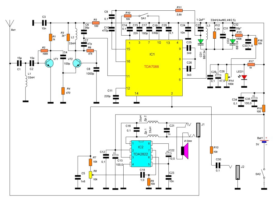
 PDF ODBIORNIK UKF FM TDA7088 POBIERZ (1,30 MB) |
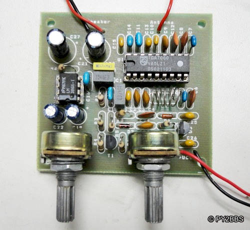
Kieszonkowy odbiornik stereofoniczny UKF FM Do budowy odbiornika wykorzystano nowoczesne układy scalone firmy Philips. Zasadnicza część odbiorcza wykorzystuje układ TDA 7088T. Jest to układ w obudowie typu SO16 przewidzianej do montażu powierzchniowego. Zawiera w swoim wnętrzu: pełny tor odbiorczy FM mono z demodulatorem, obwód wyciszania, układ automatycznego przestrajania wspópracujący z zewnętrzną diodą pojemnociową, zabezpieczenie przed odwrotną polaryzacją zasilania. Minimalne napięcie zasilania wynosi 1,8 V co pozwala na zasilanie napięciem 3 V (dwa ogniwa R6). Maksymalne napięcie zasilania nie powinno przekroczyć 5 V. Typowy pobór prądu wynosi 5,2 mA. Zakres temperatur pracy -10÷+70° C SCHEMAT TDA7088T GIF |
|
|
|
 PDF TDA7088 POBIERZ (252 KB) |
|
|
 |
Радиоприемникът в оригиналното си изпълнение беше с автоматична настройка на станциите с един бутон и допълнителен бутон за начално установяване на честотата. При стационарна работа беше много неудобно търсенето на любимите радиостанции отначало при всяко изгасяне и запускане. След като премахнах резистор в автоматиката, управляваща с напрежение варикапа за настройка, чрез 10 оборотен потенциометър радиоприемникът вече се настройва ръчно. Напрежението за настройка варира от 1,2 до 3V, при което приемания УКВ обхват е от 87,6 до 108 MHz. След това премахнах ненужните електронни елементи като светодиод, транзистор за усилвател на слушалките и превключвател с две положения за гръмкостта. SCHEMAT CD9088 LM386 GIF |
|
|
|
За бъдещи приложения бих използвал LM386 като нискочестотен усилвател, свързана по следната принципна електрическа схема: Експерименталната платка "с квадратчета" на показания усилвател се "подхвърля" два-три дни, при което я свързвах към късовълновото радио, компютър, mp3 плеър и др. звукови източници. За SMD корпус с размери 4мм х 4мм х 1мм интегралната схема се справяше добре - изходящата мощност е достатъчна за озвучаване на стая, с поносимо качество. |
 |
|
|
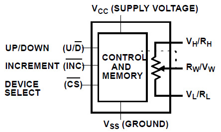
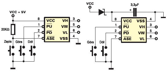 Potencjometr cyfrowy 100 k ohm PDF X9C104 POBIERZ (231 KB) PDF XICOR POBIERZ (488 KB) |
Xicor wyprodukował pierwsze potencjo− metry EEPOT w roku 1987 w technologii NMOS. Choć te pierwsze wyroby charaktery− zowały się dużym poborem energii, znalazły szereg zastosowań i przyjęły się na rynku. W roku 1992 wprowadzono drugą generację potencjometrów elektronicznych, wykona− nych w technologii CMOS, co było niewątpli− wym przełomem ze względu na zmniejszenie poboru prądu. W roku 1995 pojawiły się ukła− dy o niskim napięciu zasilania (3V). Dalszym krokiem było pojawienie się układów trzeciej generacji, charakteryzujących się mniejszymi szumami i jeszcze mniejszym poborem mocy. |
| Potencjometry firmy Xicor oznaczane są przez producenta skrótem XDCP − Xicor Digitally Controlled Potentiometer. Od dawna docenianą zaletą układów firmy Xicor jest obecność nieulotnej pamięci EEPROM, dzięki której nastawy potencjometrów są zachowywane po wyłączeniu i włączeniu zasilania. Dlatego potencjometry te oznaczane są także EEPOT lub E2POT. Potencjometr cyfrowy jest w rzeczywistości zespołem wielu (np. 100) rezystorów i przełączników CMOS. Logiczne układy sterujące włączają odpowiednie klucze odpowiednio do zawartości licznika. W praktyce w strukturze zawarte jest od 16 do 256 przełączników, a rezystorów zawsze o jeden mniej. Jeśli wszystkie rezystory składowe są jednakowe, uzyskuje się potencjometr o charakterystyce liniowej. |
 X9C104 |
|
|
 Potencjometr cyfrowy - audio PDF DS1669 POBIERZ (173 KB) |
FEATURES Replaces mechanical variable resistors Electronic interface provided for digital as well as manual control Wide differential input voltage range between 4.5 and 8V Wiper position is maintained in the absence of power Low-cost alternative to mechanical controls Applications include volume, tone, contrast, brightness, and dimmer control Available in 8-pin SOIC and 8-pin DIP packages Standard resistance values for Dallastat: DS1669-10 ~ 10 kΩ DS1669-50 ~ 50 kΩ DS1669-100 ~ 100 kΩ Operating Temperature Range Industrial: -40°C to +85°C |
|
|
|
Aircraft / Airplane Radio Receiver Component List: R1, R3 - 47K 1/4W Resistor R2 - 10K 1/4W Resistor R4 - 4.7K 1/4W Resistor R5 - 5K Linear Taper Pot R6 - 2.2K 1/4W Resistor C1, C2, C3, C6 - 0.001uF Ceramic Disc Capacitor C4 - 2.2pF Ceramic Disc Capacitor C5 - 1pF Ceramic Disc Capacitor C7 - 15uF 15V Electrolytic Capacitor C8 - 18pF Variable Capacitor D1 - 1N82 Diode Q1 - 2N918 NPN Transistor L1 - See Notes L2 - 1.8uH Inductor ANT1 - Approx. 18 Inch Wire Antenna MISC - PC Board, Wire, Knob For C8 |
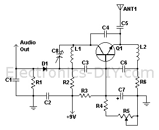
Voltage Supply: 9-12V Aircraft / Airplane Radio Receiver Operating Frequency: 220MHz - 400MHz Czytaj dalej... |
|
|
 |
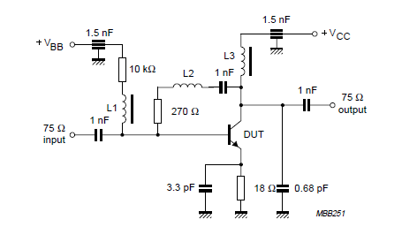
High Frequency VCO Design and Schematics
Czytaj dalej... PDF SMV1232 POBIERZ (972 KB) PDF 3296 POBIERZ (196 KB) PDF 3006 POBIERZ (182 KB) |
|
|
|
This simple transmitter allows you to broadcast on FM
radio band 87.5 - 108 MHz. It consists of a simple oscillator with
silicon planar RF PNP transistor. Directly to the oscillator an
antenna is connected. Due to the large amplitude of RF voltage is
sufficient antenna length of about 5-10 cm. I used insulated 7cm
long copper wire 1mm diameter. I eliminated the tuning capacitor,
which is usual for most bugs and miniature transmitters, because
this greatly complicates the tuning. From my own experience I know
that if you get closer to such capacitor, the operating frequency is
changed. That's why I chose to use the voltage tuning using the
Voltage Controlled Oscillator (VCO). Instead of tuning capacitor the
varicap (capacitance diode) is used, which changes its capacity by
changing the reverse DC voltage. We can tune the operating frequency
by changing the DC voltage using the trimmer P1. Varicap also
provides frequency modulation. Inductor L1 is
airborne and has six turns of 0.5 mm diameter wire wound on 3 mm
diameter. Inductor L1 with turns close together - larger inductance
- lower frequency. L1 with outstretched turns - lower inductance -
higher frequency.
Czytaj
dalej... |
Single Transistor VCO FM Transmitter PDF BBMV2101 POBIERZ (69,7 KB) PDF BBMV209 POBIERZ (63 KB) PDF BF970 POBIERZ (74,1 KB) PDF BF979 POBIERZ (71 KB) PDF BC559 POBIERZ (89,4 KB) PDF 3296 POBIERZ (196 KB) PDF 3006 POBIERZ (182 KB) |
|
|
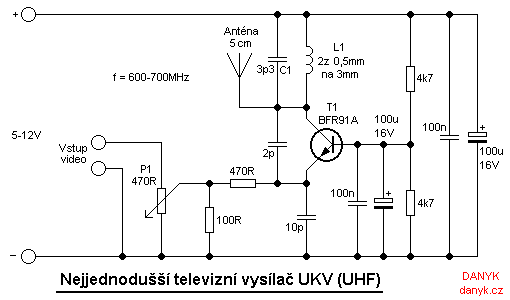 |
This simple homemade television transmitter allows you to broadcast TV picture on the UHF band 470-855 MHz. The frequency is determined by the values of components L1 and C1. The values given in the schematic diagram set the transmitter to about 600-700 MHz, that is in the range of 37. - 50. channel of analogue TV bands. The television transmitter consists of a simple oscillator with high frequency NPN transistor. Suitable are for example BFR90, BFR91A, BFR92 or BFR93. I used BFR91A in the planar to50 case. Its transition frequency is 6GHz. Carrier frequency is amplitude-modulated by the input video signal. As the video source you can use a security TV camera or camera with video output. Antenna is about 5cm (2'') of wire and is connected directly to the oscillator. The transmitted signal can be tuned on any analog TV with UHF band. Operating frequency can affect by changing values of L1 and C1. Fine tuning is possible by stretching or shrinking turns of L1. Czytaj dalej... |
|
|
|
|
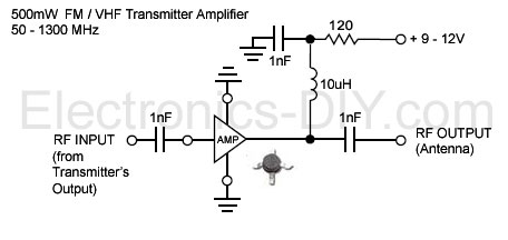
1 Watt FM Transmitter Amplifier |
|
|
|
15W Transmitter Power Amplifier 88-108MHz The power amplifier boosts 88-108MHZ 1-2W FM transmitter's power to 15 W. It includes multi-level low pass filter and has a high conversion efficiency with strong Yi-wave suppression. With good antena expected transmission coverage is at least 15Km. It uses high power 175 MHZ 4A 25W 2SC1972 RF transistor that must to be mounted to heatsink for proper heat dissipation. Czytaj dalej... |
PDF CERAMIC TRIMMER POBIERZ (633 KB) |
|
|
|
|
|
|
|
|
BFR93A NPN 6 GHz wideband transistor L1 = L3 = 5uH choke. L2 - 3 turns 0,4 mm copper wire; winding pitch 1 mm; intemal diameter 3 mm. |
 PDF BFR93A POBIERZ (121 KB) |
|
|
|
This is simple FM transmitter for FM broadcast band
in 88-108 MHz. BC 549 is small signal transistor for wide
applications, but usually for AF. You can build simple FM
transmitter with one BC549 transistor and several other component
parts. Simple FM transmitter with only one transistor is often
called bug. This project is suitable for beginners in radio amateur,
education, or hobbies. As an antenna you can connect 150cm of copper
wire. The input can be replaced with any sound source, like ipod, Mp4 player, laptop, or TV. Transistor circuit outputs 1-5 mW RF signal that can travel around 30 meters, due to limited power supply voltage, limited modulation, very loose coupling with the Antenna. The Antenna has to be connected either directly to the tank circuit or via a small capacitor. The Antenna now forms part of the tuning circuit. If you approach the antenna, the frequency of the oscillator may shift slightly. This effect is called Frequency Pulling. The frequency of operation shifts as the battery runs down. This effect is called Frequency Pushing. The internal capacitance of the transistor also changes with the temperature of the transistor. The tuning capacitor also changes values slightly with temperature. So one experiences a slow frequency drift till the transmitter reaches thermal equilibrium with its surroundings. |
Simple FM Transmitter with BC549 |
|
|
 PDF CERAMIC TRIMMER POBIERZ (633 KB) |
|
This FM radio receiver circuit is very simple to
build and is powered by just a single 1.5V battery cell. Receiver
consists of a regenerative rf stage, TR1, followed by a two of
three-stage audio amplifier, TR2 to TR4. In some areas 3 stages of
audio amplification may not be necessary, in which case TR3 and its
associated components can be omitted and the free end of capacitor
C5 connected to the collector of TR2. The critical part of the fm
radio receiver is the first stage, TR1/VC1, where the wirings must
be kept as short as possible. Coil L1 is formed by winding 8 turns
of 1mm (20 swg) enamelled copper wire on a 6 mm diameter former,
which is then removed. After that L1 should be stretched carefully
and evenly to a length of about 13mm. The tunning capacitor VC1 is one of the two fm sections of a miniature fm transistor radio with built-in trimmers (VC2). The earthy end (moving vanes and spindle) is connected to the 22pF capacitor C1. The value of the rf choke L2 is not critical, anything from 1ľH to 10ľH being suitable. The output is suitable for ordinary earphones connected in series to provide an impedance of 64Ω. Tuning-in the fm radio receiver To operate the receiver, potentiometer VR1 must first be advanced slowly (towards the end of the track connected to battery positive) until, at about the half-way point, a sudden slight increase in background noise will be heard, indicating the onset of oscillation. It then should be backed off, very slowly, until oscillation just stops; it then should be possible to tune in some stations. The correct frequency range of 87 MHz to 108 MHz can be obtained by adjusting VC2 at the high frequency (108 MHz) and slightly stretching or squeezing together the turns of coil L1 at the end (87 MHz). FM Radio Circuit Diagram fm radio receiver circuit diagram Transistors List: TR1 = BF199 TR2 = TR3 = TR4 = BC547 |
|
|
 |
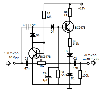
Simple microphone preamplifier
STUDIO |
|
Applications: Interface dynamic or electret microphone to a line level audio input in HIFI amplifier or computer soundcard. Power supply: 9V battery, takes less than 10 mA current Estimated component cost: Electronics components than $10 Safety considerations: No special electrical safety considerations. Circuit description This is a simple microphone preamplifier circuit which you can use between your microphone and stereo amplifier. This circuit amplifier microphone suitable for use with normal home stereo amplifier line/CD/aux/tape inputs. This microphone preamplifier can take both dynamic and electret microphone inputs (preamplifier provides power foe electret microphone elements). The idea of this circuit is to keep the design as simple as possible to be easy to build. That was my goal when I needed a simple external microphone preamplifier for my mixer. The performance of the circuit is nothing superior but can be used with many not so serious projects. The circuit is a simple one transistor amplifier with amplification of about 30-40 dB (depends on transitor, temperature and voltage). |
| The dynamic mic input is just a simple one transistor amplifier circuit with nothing special in it. LED D1 is in the circuit to show that the circuit operates. The voltage drop caused by LED (around 1.8V for RED led) has been taten in account when designing the amplifier circuit built around Q1. Resistor R4 and capacitor C5 make a filter to filter out possible noise from battery or other power source which is used to feed this circuit. Capacitors C1, C2 and C3 are used to block the DC bias on Q1 base to flow out of microphone input to microphone (the polarity of all capactors is straigh line = + and curved line = -). |
 |
|
Electret microphone input has a resistor R1 fo feeding current through electret microphone capsule when it is connected to the electret microphone input. Electret microphone needs some current (about 1 mA) flowing through it to operate, because there is a small amplifier circuit inside the microphone capsule. This circuit is suitable for all typical cheap electret capsules which available from any electronic component shop. Because electret microphones have higher signal level output, it is quite easy to overdrive the amplifier when you shout to electret microphone. |
|
|
The circuit is bet to build to a small metal box like in the picture above. Put the 9V battery inside the case too. Battery power and metal box keep external noise and interference sources away. I used standard 6.3 mm jack for dynamic microphone and 3.5 mm mono jack for electret micrphone both installed to from, panel of the metal box. The LED and power switches are also installed to front panel. Measured specifications from protype Frequency response: 20 Hz to 20 kHz +-1dB Noise level (A-weighted): -85 dBm Amplification: 35 dB Because of the simplicity of the design the distortion performance is not very good. |
|
|
|
|
At signal levels typically used by electret microphones the distortion is about 2-3%. With dynamic microphones the distortion level is lower (not measured). Here is the frequency response as measured by LoudSpeaker LAB software DEMO version with Sound Blaster 16 PNP card: The bass frequency attenuation is caused by the microphone preamplifier circuit. The high end attenuation is caused by Sound Blaster 16 card. As seen in the measured performance, the microphone preamplifier is suitable for speaker measurements made using suitable measurement software and sound card. Using this preamplifier connected to line level input the problems caused by poor microphone preamplifier in many sound cards can be avoided. Component list R1 4.7 kohm R2 220 kohm R3 2.2 kohm R4 120 ohm C1..C4 10 uF 16V electrolytic C5 100 uF 16V electrolytic D1 Red LED Q1 BC547B SW1 on/off switch If you can't find all the components on the shop near you take a look at component replacement tips. |
|
If you happen to have hard time finding BC547 transistor, you can use 2N2222 transistor instead. The circuit has been reported to work well with it also (although there might be some slight performance changes though, I have not tested and mearured the circuit with 2N2222). Modification ideas If you plan to use this circuit with a soundcard electret microphone which has 3.5 mm stereo plug, then you have modify the circuit to make it work work this type of multimedia microphone. You don't have to make many changes: just replace the 3.5 mm mono jack with stereo jack. In the original circuit R1 goes to the tip of the microphone connector, but now you connect R1 to go to the ring of the connector. If you want an adjustable output signal level for the microphone preamplifier you can add this quit easily by connecting one 10 kohm logarithmic potentiometer to the circuit output in the following way: |
|
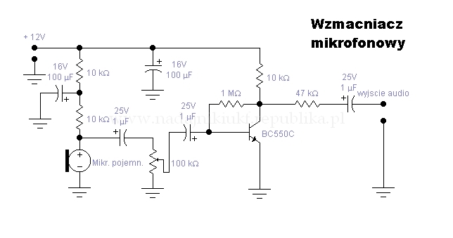
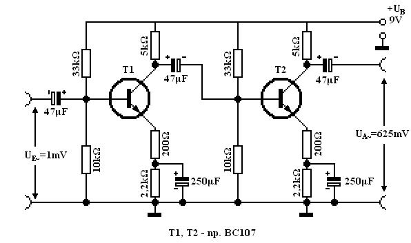
Przedwzmacniacz. W schemacie poniżej połączono szeregowo dwa stopnie tranzystorowe - T1 i T2. Wzmocnienie napięciowe jednego stopnia może wynosić 25. Gdy mamy do czynienia z dwoma stopniami połączonymi szeregowo, całkowite wzmocnienie obu stopni jest równe iloczynowi wzmocnień poszczególnych stopni, czyli: 25 x 25 = 625. Przy napięciu wejściowym pierwszego stopnia wynoszącym 1mV na wyjściu stopnia drugiego otrzymamy sygnał około 625 mV - wystarczający do wysterowania wzmacniacza głośnikowego. |
 |
|
|
|
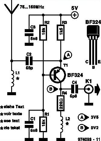
This inexpensive FM radio receiver antenna booster
uses the BF324 TO92 style pnp transistor in a grounded-base
configuration. The circuit may be used as a signal booster with VHF
receivers whose front end suffers from low sensitivity (such as many
valved and army surplus types). The frequency range of the
preamplifier is roughly from 75MHz to 150MHz. The two inductors in the circuit are home made. L1 consists of 10turns of 24SWG enamelled copper wire; the internal diameter is 3mm, no core. Inductor L2 has 13 turns of the same wire, and an internal diameter of 5mm; no core is used either. A construction tip: close-wind the inductors using 3 and 5mm drill bits respectively as temporary formers. The prototype of the preamplifier was successfully used with an 88-108 MHz FM broadcast receiver and a 2-metre VHF ham receiver. The preamplifier draws about 2.5mA from a 5-volt supply. Wideband FM antenna booster circuit schematic
|
 |

|
|
|
|
Wideband Active Antenna Circuit |

|
|
|
UHF Antenna Amplifier Circuit This amplifier circuit is used to amplify TV signals in UHF range. It uses a low-noise transistor and gives 10 to 15 dB amplification in the frequency range from 400 MHz to 850 MHz. The transistor must be shielded from the input components and in constructing this circuit, the wirings must be as short as possible. For best results, the cable must be directly soldered to the PCB. The circuit should be installed near the antenna and housed in a water proofed case. The power supply for this uhf tv antenna amplifier is fed through the cable by using a choke coil. To prevent the DC voltage from getting into the TV set, the coaxial cable must be coupled to the set through a small value capacitor. To align the amplifier, just adjust P1 until the best reception is achieved. It means a collector current between 5 and 15 mA. PCB 1 PCB 2 |
 |
|
|
|
|
|
|
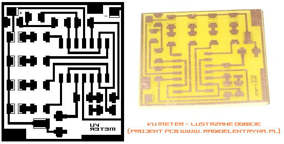
 Linijka świetla (wskaźnik wysterowania) VU-METER POBIERZ PCB OFFICE (15,5KB) |
|
|
|
 |
 |
 |
| Kompresor dynamiki 1 D1,D2 - dowolny BYP. AAP152 (germanowa), 1N4148 (przełączająca). | Kompresor dynamiki 2 | Kompresor dynamiki 3 D1,D2 - dowolny BYP. AAP152 (germanowa), 1N4148 (przełączająca). |
|
|
 |
 |
 |
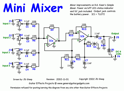
| Mini Mixer - cztery kanały wejściowe (monofoniczny). |
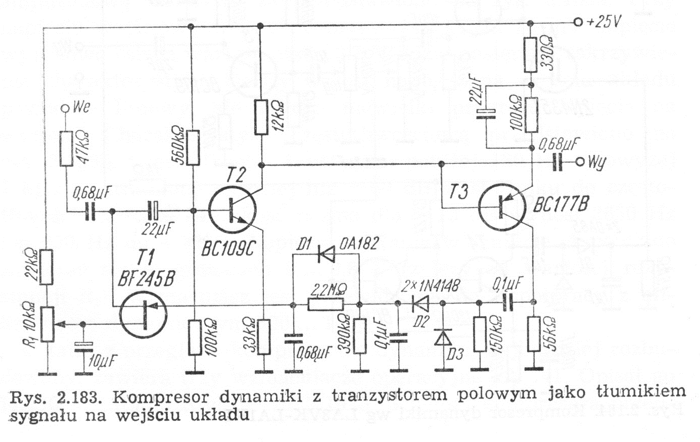
Procesor dynamiki z tranzystorem polowym jako tłumikiem sygnału na wejściu układu. |
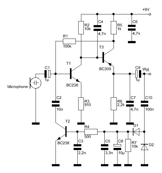
Mikrofonowy kompresor dynamiki. |
|
|
|
Audio limiter components R1 = 100K R2 = 1K R3 = 1M R4 = 68K R5 = 10K C1 = 10uF C2 = 680nF T1 = BFW11 T2 = BC173C IC = BA741 |
 |
|
|
 |
|

|
|
| Automatic Gain Control or AGC is a circuit design which maintain the same level of amplification for sound or radio frequency. If the signal is too low the.. |
 |
|
|
|
|
|

|
|
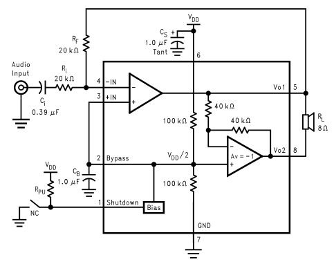 |
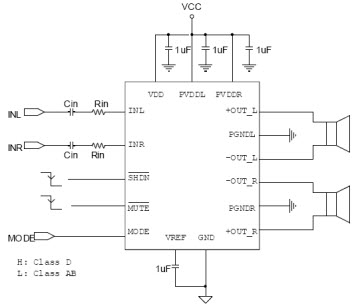
LM4871 3W Audio Power Amplifier with Shutdown Mode Boomer audio power amplifiers are designed specifically to provide high power, high fidelity audio. They require few external components and operate on low supply voltages from 2.0V to 5.5V.
|
|
|
|
Profi minőségű kisméretű rádióadó. A tekercsadatok: minden tekercs 4 mm átmérőre készül 0,6 mm-es rézhuzalból. L1: 6 menet L2: 2-3 menet L3: 7 menet A mikrofon jelét a BC184 típusú tranzisztor erősíti fel. A két dióda bármilyen AA típusú dióda lehet, szerepük a túlvezérlés megakadályozása. Az innen kijövő hangfrekvenciás jelet az első BF224 illeszti, és a másik BF224 pedig felerősíti az antenna számára. Az utolsó BF224-es fokozatot árnyékoló lemezzel kell fedni, csak az antenna lóghat ki belőle! PDF BF224 POBIERZ (152KB) |
 |
|
|
|
|
500mW PLL FM Transmitter 88-108MHz This PLL transmitter is controlled and the frequency is very stable and can be programmed digitally. Transmitter will work 88-108 MHz and output power up to 500mW. With a small change can set the frequency of 50-150 MHz. The output power is often set to several watts with transistors. So therefore I decided to build a simple transmitter with great performances. The frequency of this transmitter can easily be changed by software and space / compress air coil. This transmitter is the oscillator colpitts. Oscillator is a VCO (voltage controlled oscillator) which is set by the PLL circuit and PIC micro controller. This oscillator is called the Colpitts oscillator and voltage controlled to achieve the FM (frequency modulation) and PLL control. Czytaj dalej... |
|
|
|
FM Synchro Receiver With capacitive three-point oscillator FM Synchro Receiver Small VHF receivers needn‘t employ complex FM demodulation circuitry nor be double superhets. Using a capacitive three-point oscillator in common-base mode as the synchro demodulator makes things a lot easier. |
 |
|
|
|
|
2N3904 |
|
|
|
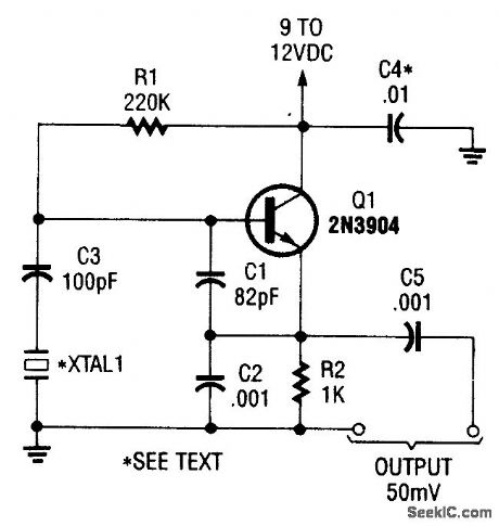
Crystal Sine Wave Oscillators |
|
|
|
|
|
Crystal oscillators can produce
either sine wave or square wave outputs over a very wide |
|
|
|
The updated circuit uses one of the latest third overtone crystals. These offer greater reliability than the fifth overtone crystals commonly used in oscillator circuits at VHF. Czytaj więcej... |
|
|
|
|
|
|
|
|
Kwarcowy Tx z modulacją AM. Generator odpala bezproblemowo. |
|
|
|
 |
Transmitter - 2n2222. Rezonator ceramiczny (kwarcowy) kryształ. |
|
|
| Generator BC547. Rezonator ceramiczny (kwarcowy) kryształ. |
 |
|
|
 |
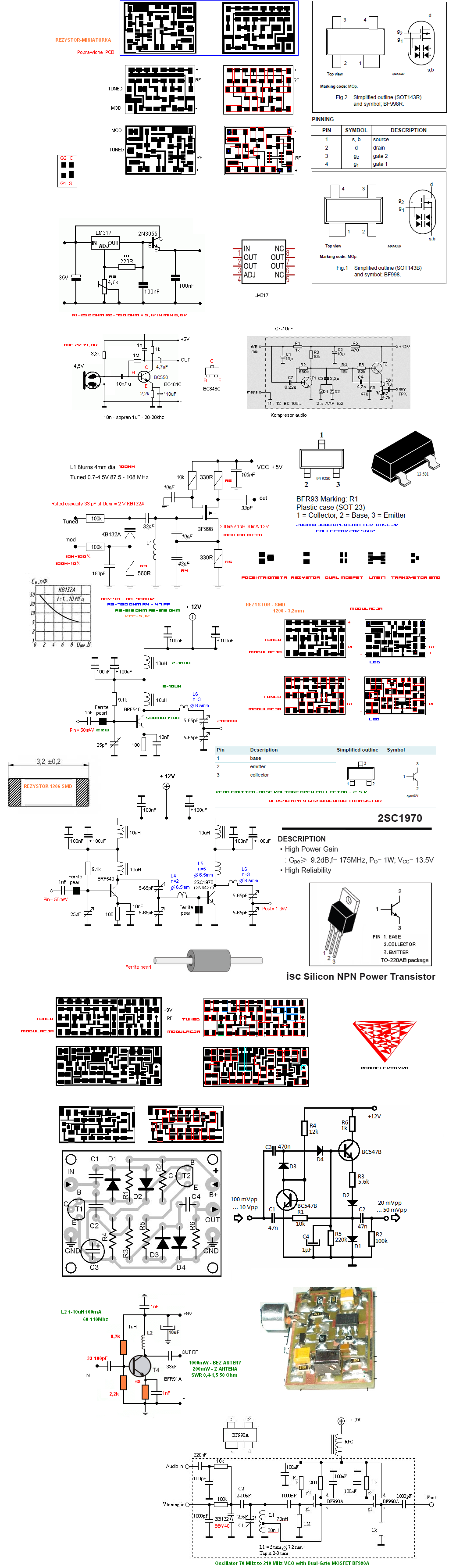
Oscillator 70 MHz to 210 MHz VCO with Dual-Gate MOSFET BF990A |
|
|
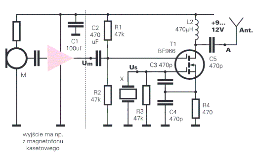
| Nadajnik Am. X - 4Mhz. Dual Mosfet BF966. 9 - 12V. |
 |
|
|
 |
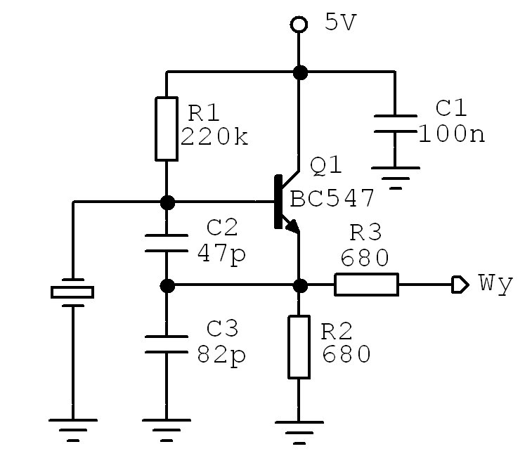
Oscillator 48Mhz. BC547 NPN. 5 - 12V. Rezonator ceramiczny (kwarcowy) kryształ. |
|
|
| Mieszacz (modulator) na kanał 5 Audio/Video. BF494. 3V. |
 |
|
|
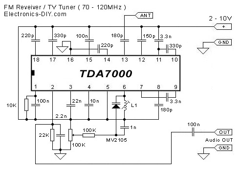 |
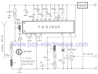
FM Receiver / TV Tuner TDA7000 This simple one chip FM receiver / TV tuner will acquiesce you to accept frequencies from 70 up to 120MHz. With this baby receiver it is accessible to auto TV stations, absolute 88 - 108MHz FM band, aircraft chat and abounding added clandestine transmissions. It is a absolute accompaniment to any FM Transmitter abnormally if FM bandage in your breadth is actual crowded. TDA7000 receiver offers actual acceptable acuteness accordingly it will alike acquiesce you to auto weaker signals that cannot be heard on accepted FM receivers. A accurate affection of presented TDA7000 FM receiver is a voltage controlled oscillator agnate to TV tuners that are acclimated in television sets. Abundance is acquainted by capricious the ascribe voltage to the oscillator. The advantage of this blazon of oscillator is that you can use approved 100K potentiometer to absolutely tune to a accustomed broadcast. Tuning can be performed abundant quicker and absolutely than by application a trimmer (variable capacitor). Trimmers will additionally about-face the abundance as you blow them area potentiometer will not. Trimmer additionally needs to be placed on receivers PCB to abbreviate the devious capacitance area potentiometer can be calmly placed anywhere you appetite because it will not be afflicted by any alien capacitance. Czytaj dalej... |
|
|
|
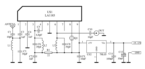
Konwerter umożliwia odbiór stacji nadających w paśmie
88-108 MHz, na odbiornikach posiadających tylko dolny zakres UKF
(66-74 MHz).Konwerter zbudowany jest na jednym układzie scalonym LA1185. Układ ten produkowany jest przez firmę SANYO, zawiera w swojej strukturze praktycznie wszystkie człony głowicy UKF: wzmacniacz w.cz, mieszacz, oscylator. Układ scalony TA7358AP = LA1185 POBIERZ J-246 PDF (862KB) |
 |
|
|
 |
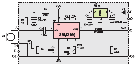
Limiter  Kondensator tantalowy Technické parametry Napájecí napětí: 10-14 V stabilizované Napájecí proud: 20 mA Audio vstup: impedance 20 kOhm, volitelná preemfáze Výstupní napětí: 0,4 V rms Zpracovatelný dynamický rozsah: >50 dB Czytaj dalej... |
|
|
|
|
|
Parametry:
|
 |
|
|
|
|
|
|
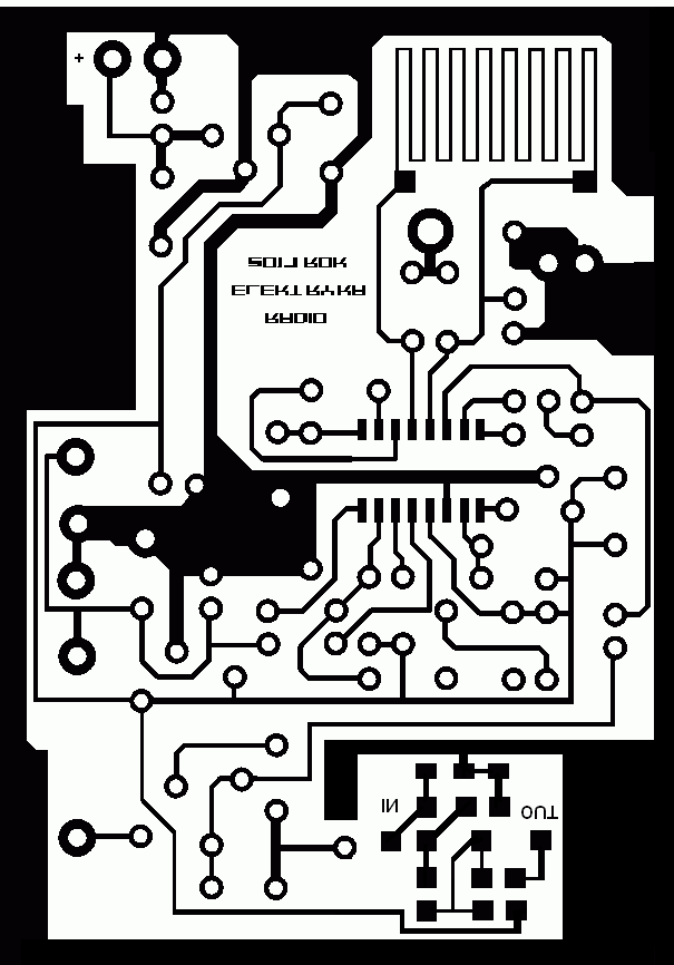 Lustrzane odbicie zmodyfikowanej pcb (odbiornik plus przedwzmacniacz antenowy). |
 Cewkę L2 obwodu heterodyny nawinięto na korpusie z filtru 7 x 7. Uzwojenie ma 4 zwoje drutu CuAg fi 0,8. (36nH) |
|
|
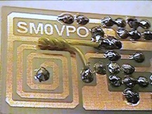
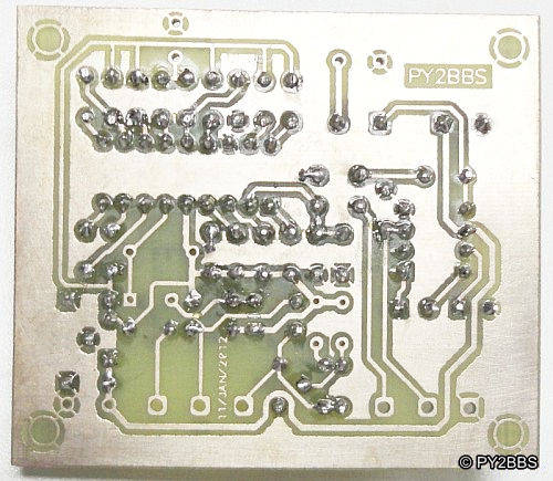
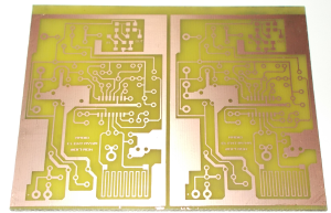 Wytrawiona pcb. www.radioelektryka.glt.pl |
|
|
|
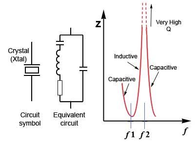
| Pierce Oscillator Circuit Circuits Next Gr Modified Crystal Inverter Calculator George Washington Transistor Design Gate Jfet Example |
 |
|
|
 |
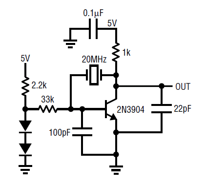
The Pierce Oscillator Crystal-controlled Pierce
oscillator circuit. The circuit shown to the right is known as a Pierce oscillator. This is a simple, very conventional oscillator circuit, which works quite well as long as the transistor doesn't generate too much noise. Feedback is through the crystal, of course, and the operating frequency is trimmed by adjusting C1. Of course, the circuit cannot be tuned over a range, but it does lend itself to switching between different crystals, thus allowing this oscillator to cover different frequency bands. C2 serves to bypass some of the feedback energy, and thereby keep the output sine wave cleaner. Without C2, the output waveform would be more of a square wave than a sine wave.The Pierce oscillator typically is built using a parallel mode crystal operating at its fundamental frequency. |
|
|
|
2N3904 XTAL Oscillator 20 MHz POBIERZ Application Note 12 PDF (122 KB) |
 |
|
|
 |
Colpitts crystal oscillator This type of Crystal Oscillators are designed around a common collector (emitter-follower) amplifier. The R1 and R2 resistor network sets the DC bias level on the Base while emitter resistor RE sets the output voltage level. Resistor R2 is set as large as possible to prevent loading to the parallel connected crystal. The transistor, a 2N4265 is a general purpose NPN transistor connected in a common collector configuration and is capable of operating at switching speeds in excess of 100Mhz, well above the crystals fundamental frequency which can be between about 1MHz and 5MHz. The circuit diagram above of the Colpitts Crystal Oscillator circuit shows that capacitors, C1 and C2 shunt the output of the transistor which reduces the feedback signal. Therefore, the gain of the transistor limits the maximum values of C1 and C2. The output amplitude should be kept low in order to avoid excessive power dissipation in the crystal otherwise could destroy itself by excessive vibration. |
|
|
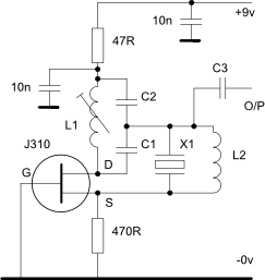
| Solid State Circuits 2 - RF Oscillators Crystal Oscillator This circuit can be used from low frequencies to at least 120MHz using series resonant crystals on their fundamental or overtone mode. The output can be taken from the feedback tap as shown, a low impedance winding on L2 or from the drain of the J310 via a low value capacitor. The following stage should be used a a buffer to isolate subsequent stages from the oscillator. The combined series value of C1 and C2 resonates with inductor L1 at the desired frequency and crystal X1 must have a fundamental or overtone series resonance as appropriate at the same frequency. C2 is about five times the value of C1 Inductor L2 is generally only required at frequencies above about 60MHz and must be chosen to resonate with the total parallel capacitance of X1 at the frequency of oscillation. If the circuit shows signs of free running oscillation controlled by L1 then L2 will be required. The parallel capacitance of X1 will typically be 4 - 6pF at frequencies of 60MHz or more. |
 |
|
|
 |
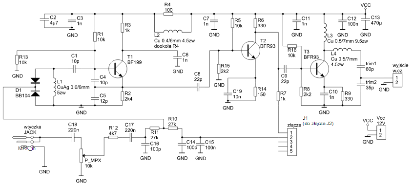
Generatora FM wraz z separatorami. A generator jak to generator... Powinien być sztywno zmontowany, zaekranowany na 'amen' i w ogóle przy jego budowie powinniście się stosować do zaleceń, jakie można znaleźć w różnych miejscach na naszej stronie. Cewka L1 to ok. 5zw. 1mmCuAg na śr. 5mm (górne pasmo UKF), z odczepem w połowie cewki. Można np. przylutować tu bezpośrednio nożkę kondensatora 2p. 88-108MHz. |
|
|
|
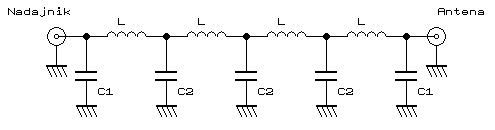
Schemat - 4 stopni wzmacniających. Jeśli już jesteś bogaty w wiedzę, zerknij na wartości cewek: (dane dla ok. 104 MHz) L1 - 7zw. 1mmCuAg na śr. 5mm L2 - 6zw. 1mmCuAg na śr. 5mm L3 - 5zw. 1mmCuAg na śr. 5mm L4 - 2zw. 1mmCuAg na śr. 5mm L5 - 5zw. 1mmCuAg na śr. 5mm L6 - 5zw. 1mmCuAg na śr. 5mm Dł1 - 5zw. DNE 0.3 na pierścionku ferrytowym, lub ew. na pręciku ferrytowym o śr. 3mm Jeżeli przy procedurze strojenia nadajnika za pomocą trymerów dopasowywujących między stopniami któryś z nich ustawi sie w krańcowej pozycji (1 szczyt), warto zaeksperymentować z cewkami. No a stroić należy standardowo, za pomocą sztucznego obciążenia (75 lub 50 Ohm w zależności od instalacji antenowej) i podłączonej do niego sondy w.cz. |
 |
|
|
|
To jeszcze jednak nie koniec, trzeba je zestroić i sprawdzić poprawność działania. Można to zrobić za pomocą odbiornika który może odbierać na częstotliwości 2x nasza częstotliwość nadawania, czyli np. za pomocą skanera. Wartości elementów dla impedancji nadajnika, przewodu koncentrycznego i anteny 75 Ohm, oraz częstotliwości nadawania F <~ 106MHz: L = 225nH ~ 6zw., śr. cewki 7.7mm, drutem 1mm CuAg, długość nawinięcia ok. 8mm C1 = 20p C2 = 40p |
|
|
|
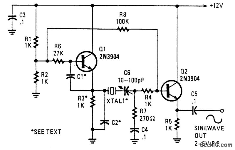
Wireless Microphone FM Transmitter This Wireless Microphone FM Transmitter has been a very popular project with beginners and experienced constructors alike. It has been used inside guitars and as the basis of a remote control system. I do however, receive many requests for a higher powered circuit and better microphone sensitivity. Now I can introduce the new FM Wireless Microphone, which also has a better frequency stability, over 1Km range (under ideal conditions) and is good on microphone sensitivity. This has been achieved by adding an RF amplifier buffer (with 10dB gain) and an AF preamplifier to boost the modulation a little. |
 |
 |
|
|
|
Construction is quite simple. L1 is 3.25 turns in spiral form and is an integral part of the PCB foil pattern. The two BC547 transistors can be replaced with (almost) any small-signal NPN transistor, such as the 2N2222. The final stage is a BC557 PNP general purpose device. If you use different devices then you should select the 1M0 resistor for 5-volts DC at the collector of the the first transistor. Select the 47K resistor for 3 - 4 volts on the collector of the third transistor. Here is the V5 component overlay drawing. Note that there is a modification: PCB Office Word. |
 |
 |
|
|
|
There used to be a 1n0 5mm cap for supply decoupling, but after a cange of component supplier (manufacturer?) there developed some form of RF instability when the gain of the PA transistor was a little above normal. Replacing the 1n0 to an electrolytic capacitor of 22uf cured this problem totally. Any "radial" (the leads both come out of the same end) type electrolytic capacitor from 0.47uf upwards cures the problem. The finished unit draws about 30mA which should vary as you touch the tuned circuit, a good test that the unit is oscillating. You should remove the 4K7 resistor if you use a dynamic microphone. |
 |
 |
|
|
|
The PCB is 50mm x 25mm, a little larger than the first version but there are three stages instead of just the one. The first prototype is shown above, beside the battery powering it. The output power is about +10dBm which is about 10dB more than the first FM Wireless Microphone. This would theoretically give it 3.12 times the range (1.6Km) but I have only tested it using a handheld receiver with the TX laying on the bench indoors. But I got a comfortable 700 meters (and a few funny looks from our neighbours). |
|
|
|
|
|
|
Above you can see the addition of a
"gimmick" capacitor added across the 12p tuning capacitor to lower
the frequency of the transmitter. Make the capacitor by twisting two
lengths of single core insulated hook-up wire, about 2cm long. This
will reduce the frequency to the bottom end of the band. Cut short
the capacitor to increase the frequency to the desired final
frequency. If you cut it a few KHz too high then just twist the
gimmick a little tighter. |
|
|
|
|
|
|
|
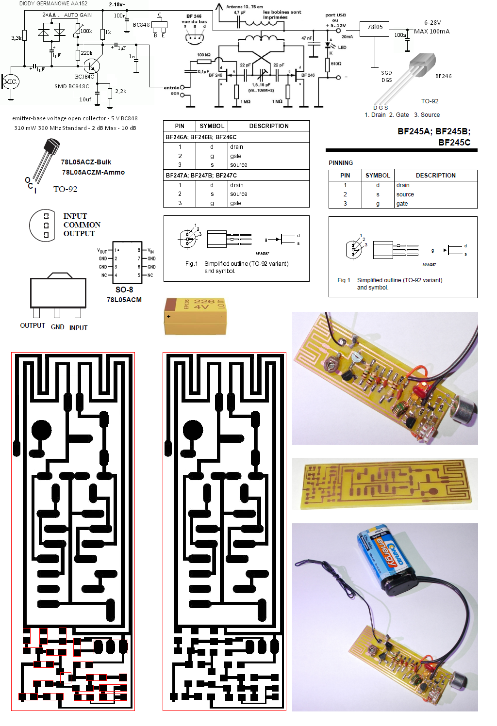
USB Mono FM Transmitter This small FM
transmitter with a range of about 50 meters designed for connection
to the USB port. With lots of mini-transmitters then you have a
comprehensive, action-packed radio program. Due to the power supply
via the USB port of a high frequency stability is achieved.
Alternatively, the receiver, a battery 5 to 12 volts to operate. FM Transmitter Construction USB FM Transmitter Prototype It is
not necessary to drill the transmitter PCB. All components will be
soldered to the plate with their legs folded, like this: The two
transistors and the LEDs are polarized: The transistor has a flat
side, the LED a foot longer than the other is the anode (A), the
other is the cathode (K). The audio cable (minijack) must be
transformed from a stereo cable into a cable. Mono Sound: Soldering together the white and red cables, leaving
aside the yellow cable (mass). The frequency setting will be turning
the variable capacitor gently with a screwdriver or thin cardboard
but rigid.
PDF BF246B POBIERZ (105 KB)
PDF
BF245A-B-C POBIERZ (288 KB)
PDF BF247 GIF
(28 KB) PNG TRANSMITTER PRZEDWZMACNIACZ |
|
|
|
 |
|
|
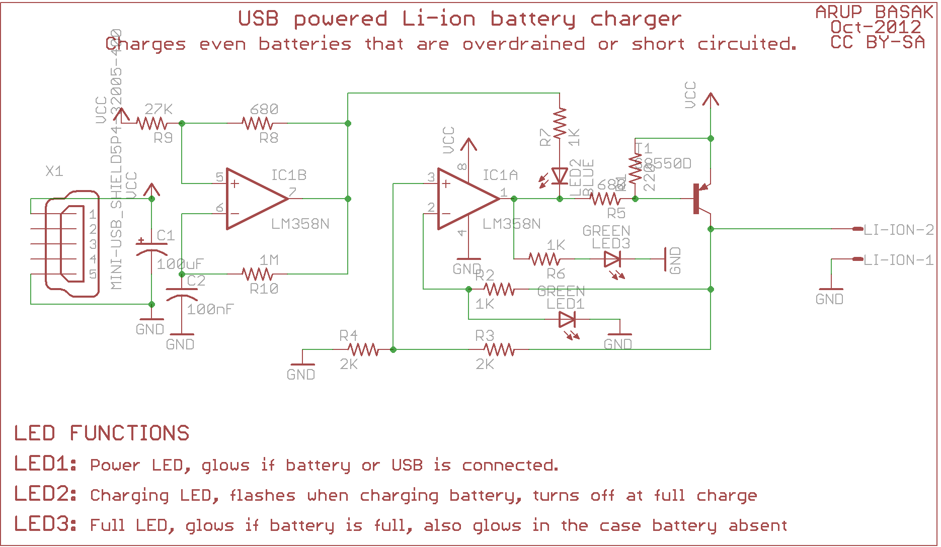 |
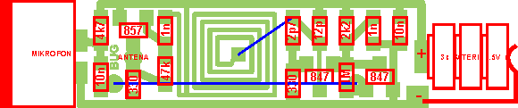
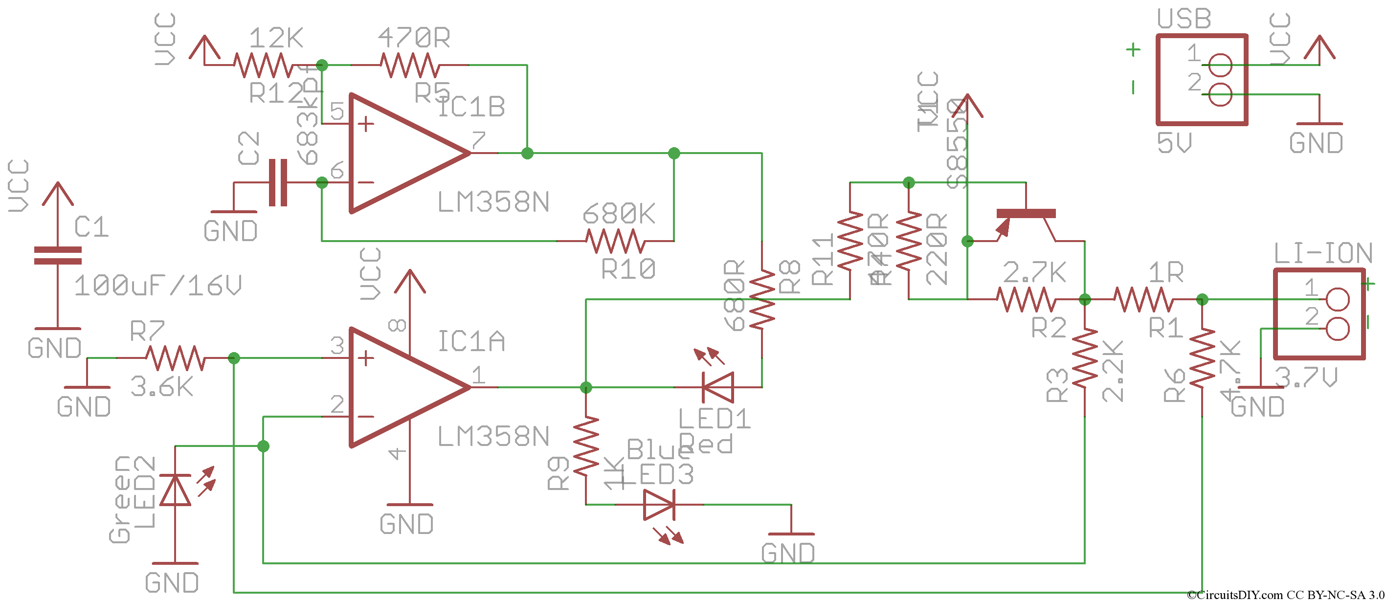
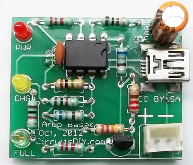
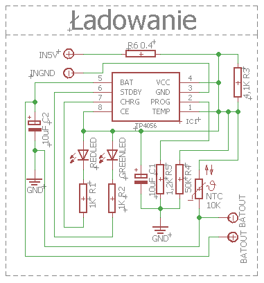
USB li-ion charger This is a simple li-ion charger
without a dedicated li-ion charger IC. This circuit can be used to
efficiently and intelligently charge any single cell Li-ion battery
pack like mobile battery, digicam battery, etc. Features: Charging
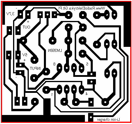
via mini-USB connector which is very common. Charging status display by LED Simple circuit by using opamp, resistor, and not by any complex dedicated IC or micro-controller. Charges completely drained (0V) battery packs. Max charging current 500mA(limited by USB supply), depending on battery. Here’s the corrected schematics and the board design of the circuit. PL. Led świeci jak rozładowana. Led mruga jak ładuje. Led świeci jak naladowana. Power led świeci gdy podłączone zasilanie. |
|
|
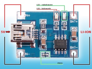
| This is a simple li-ion charger without a dedicated li-ion charger IC. This circuit can be used to efficiently and intelligently charge any single cell Li-ion battery pack like mobile battery, digicam battery, etc. There are 3 LED on the circuit. One LED will be always on whenever a battery is connected. Another LED will blink continuously to indicate charging and the third LED will glow when battery charge complete. We can charge these Li-ion battery packs with direct regulated voltage but these batteries require special charging technique for long lasting. These are than when battery charge is less than 20%, charging voltage should be low, not a constant and when battery is full, i.e, charging current almost zero, charging should stop. In this circuit, the both conditions are checked with the 1R resistor which is in series with the battery. |
 |
|
|
 |
|
|
|
|
Features: Charging via mini-USB connector which is very common. Charging status display by LED Simple circuit by using opamp, resistor, and not by any complex dedicated IC or micro-controller. Charges completely drained (0V) battery packs. Max charging current 500mA(limited by USB supply), depending on battery. Here’s the corrected schematics and the board design of the circuit. PDF BC556B-D POBIERZ (81,2KB) |
 |
|
|
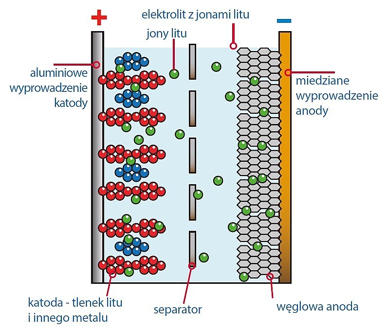 |
Akumulatory litowe pojawiły się na rynku dopiero w roku 1991, czyli ponad sto lat po wynalezieniu akumulatorów niklowo-kadmowych i kwasowo-ołowiowych. Zastosowane najpierw w sprzęcie przenośnym Sony, szybko zaczęły się upowszechniać i dziś powszechnie dostępne są różne odmiany akumulatorów litowo-jonowych. |
|
|
| Ich popularność bardzo szybko rośnie. Są powszechnie stosowane w telefonach komórkowych, tabletach, laptopach, aparatach fotograficznych, elektronarzędziach, a także w samochodach elektrycznych i hybrydowych. W modelarstwie wydajne akumulatory litowe pozwoliły na zastosowanie wydajnych silników elektrycznych do napędu modeli. POBIERZ AKUMULATOR LITOWY PDF (2,59 MB) |
 |
|
|
|
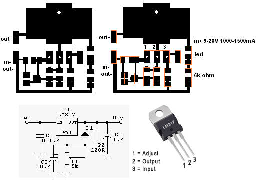
|
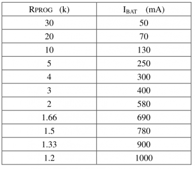
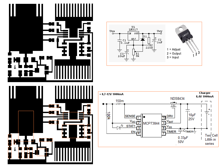
"Napięcie wejściowe stabilizowane
jest do poziomu 4.17V przez LM317. Ładuje ono akumulator. Rezystor
R3 pełni rolę ogranicznika prądowego i rezystora pomiaru prądu.
Napięcie które się na nim odkłada porównywane jest z wartością
ustawioną przez potencjometr I_ADJ i jeśli spadnie poniżej, zapali
diodę. |

|
|
|
|

|
|
|
 |
|
|
 |
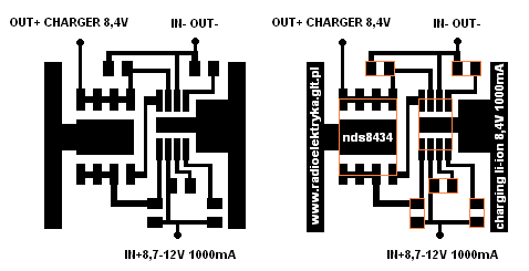
Charging 8,4V Vyrovnávací obvod pro nabíjení dvou článků Li-ion s rozdílnou kapacitou Balance circuit for charging two Li-ion cells with small capacity differece. Neustále dostávám dotazy, zda lze nabíjet více článků zapojených v sérii. Akumulátory v sérii nabíjet lze, stačí upravit odpor rezistorů R4 a R5 tak, aby na výstupu bylo stabilizované napětí 2x nebo 3x 4,2 V - podle počtu článků. Můžete také upravit odpor R2 a zvětšit tak nabíjecí proud. Před stabilizátorem (na kondenzátoru C1) musí být napětí nejméně o 3 až 4 V větší, takže je třeba použít jiný transformátor. Pro nabíjení celého paku je nutné, aby všechny akumulátory byly shodné!! V praxi tomu tak není. I když byly možná akumulátory původně vybrány tak, aby byly jejich parametry shodné, stárnutí se projeví u každého jinak. |
|
|
|
Simple Li-ion charger O akumulátory Li-ion jsem se začal intenzivněji zajímat loni v létě, když se mi podařilo přivézt si z dovolené telefon bez nabíječky. Po několika experimentech vzniklo zapojení na obr. 1, které se velmi osvědčilo. Zapojení zajišťuje fázi nabíjení omezeným proudem a konstantním napětím.  |
 |
|
|
 PDF MCP73864 POBIERZ (844 KB) PDF LI-ION 8,4V POBIERZ (372KB) PCB CHARGER POBIERZ (60,9KB) PCB CHARGER MOT POBIERZ (35,9KB) |
 Charging 8.4V1 ,2A Li-ion |
|
|
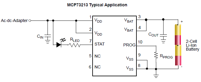 |
Charging 8,4V 1100mA Li-ion PDF MCP73213 POBIERZ (510KB) |
|
|
 |
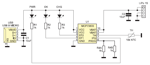 PDF ŁADOWARKA LI-PO POBIERZ (1,09MB) PDF MCP73833 POBIERZ (1,5MB) |
|
|
Four Preset Voltage Regulation Options: - 8.2V - MCP73842-8.2, MCP73844-8.2 - 8.4V - MCP73842-8.4, MCP73844-8.4 |
Advanced Single or Dual Cell
Lithium-Ion/Lithium-Polymer Charge Management Controllers 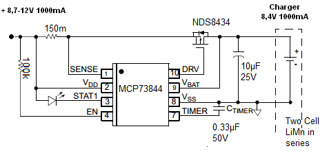 |
|
|
|
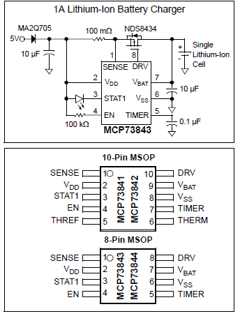
PDF MCP73844 POBIERZ (392KB)
PDF NDS8434 POBIERZ (294KB) PDF MA2Q705 POBIERZ (230KB) PCB MCP73844 POBIERZ ODBICIE LUSTRZANE (16KB) |
 |
|
|
|
|
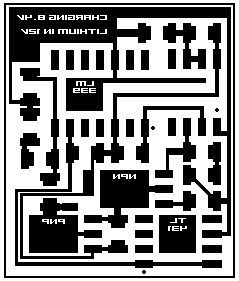
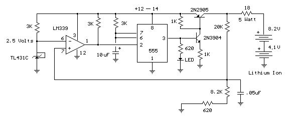 PDF TL431 POBIERZ (2,41MB) PDF 2N2905 POBIERZ (145KB) PDF 2N3904 POBIERZ (60,8KB) |
2 Cell Lithium Ion Charger Description This circuit was build to charge a couple series Lithium cells (3.6 volts each, 1 Amp Hour capacity) installed in a portable transistor radio. The charger operates by supplying a short current pulse through a series resistor and then monitoring the battery voltage to determine if another pulse is required. The current can be adjusted by changing the series resistor or adjusting the input voltage. When the battery is low, the current pulses are spaced close together so that a somewhat constant current is present. As the batteries reach full charge, the pulses are spaced farther apart and the full charge condition is indicated by the LED blinking at a slower rate. |
|
|
|
 |
Regulowany stabilizator impulsowy 0…25 V, 0…5 A Układ to kompletny moduł wykonawczy impulsowego regulatora napięcia. Może pracować, jako samodzielny stabilizator lub jako element zasilacza warsztatowego. Można go sterować zdalnie – podanie na odpowiednie złącze napięcia 5V spowoduje wyłączenie układu. Rekomendacje: Urządzenie szczególnie polecane do zasilania urządzeń elektronicznych oraz do pracowni elektronicznej PDF AVT1522 POBIERZ (1,85MB) |
|
|
|
Transmitter 87,5 - 108 Mhz Pobierz PCB A Pobierz PCB B Pobierz PCB C-D Pobierz Schemat blokowy |
|
|
|
|
|
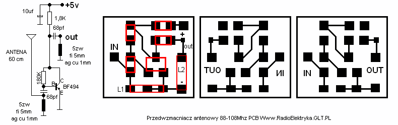
Przedwzmacniacz antenowy 88 - 108 Mhz FM. Zasilanie 5 - 9V. PCB RadioElektryka. |
|
|
| This amplifier circuit can be used to amplify VHF television signals. The gain is between 5dB and 28dB. 300ohm twin feeder can be used for the In/Out leads. PL Ten obwód wzmacniacza może być używany by rozszerzyć VHF telewizji sygnały. Zysk jest między 5dB a 28dB. 300ohm linia dwutorowa może być używana dla W/Z prowadzi. |
 |
|
|
| Przetwornica napięcia MC340663. |
 |
|
|
 |
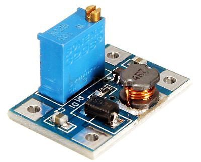
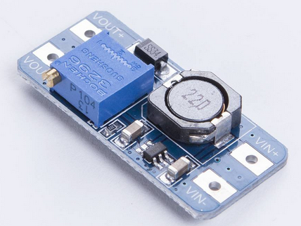
This simple DC/DC step-down converter is perfect for breadboard design or replacement of 78xx stabilizers. It's not so powerful but it can give about 350mA and even if you apply higher input woltage, it doesn't get much hot like the 78xx ones. The pinout is the same like in 7805. I've made bigger pads for capacitors or inductor so you can solder almost anything size :) Theoreticaly the input voltage can be 40V according to the datasheet. You have to be careful and select proper input capacitor of suitable voltage. Also instead of SMD inductor you can use bigger thru-hole types. If you would like recalculate values or change output voltage, you can use this online MC34063 calculator. Download archive with eagle project and Inkscape PCB files are on the bottom of this page. POBIERZ PCB. |
|
|
| Przetwornica napięcia MC34063A 6-14V/28V. |
 |
|
|
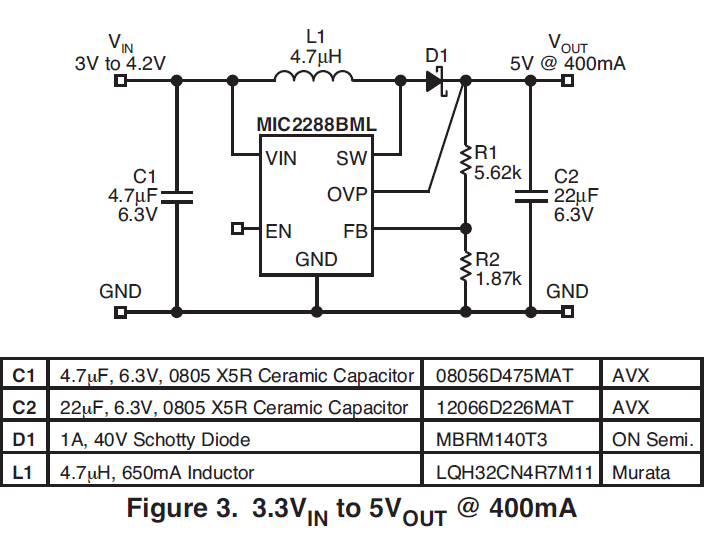 |
Przetwornica napięcia 3-4,2V/5V 400mA |
|
|
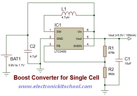
| Przetwornica napięcia 0,9-1,7V/3,3V 100mA LTC3400. |
 |
|
|
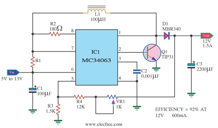 |
Przetwornica napięcia 5-13V/12V 1,5A MC34063. |
|
|
| Przetwornica napięcia 5-15V/50V MC34063A. PDF MC34063A POBIERZ (1,15 MB) |
 |
|
|
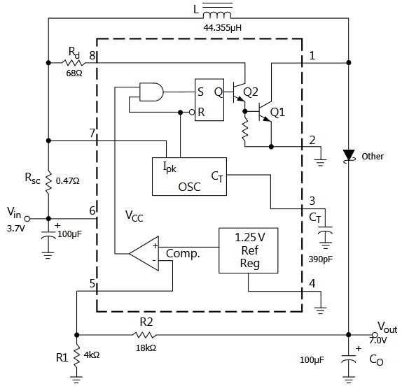 |
Przetwornica napięcia 3,7V 70mA/7V 30mA Li-ion. MC34063.
The current sense resistor MUST be there, otherwise the chip will pass away during the very first pulse. Rsc 0R22 is a safe value - if you use bigger one e.g. 0R5 , then you'll have a limited "ON" current through the inductor. that shouldn't be a problem in step-down configuration, but for step-up you need more current - so go for a smaller sense resistor. the chip will work well even with different than calculated inductors (+- 50%), but your max output current and voltage ripple on the output will be altered significantly. |
|
|
|
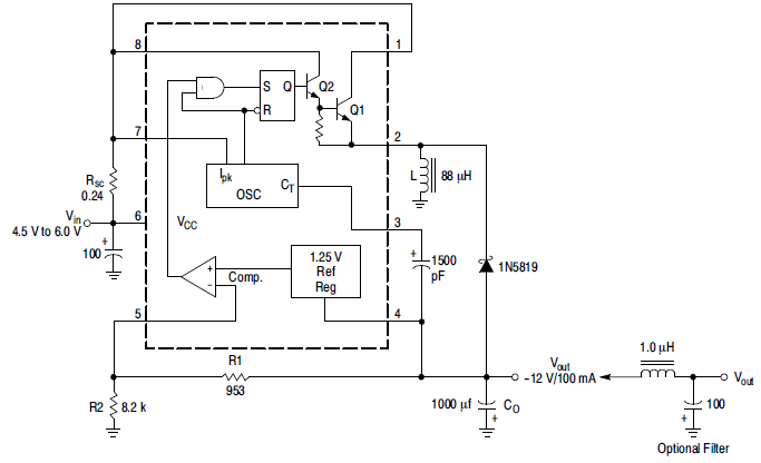
Przetwornica napięcia (zalecany schemat) 4,5-6V/-12V
30mA MC34063A, MC33063A, SC34063A, SC33063A, NCV33063A |
 |
|
|
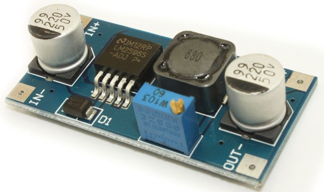 Przetwornica DC DC LM2577 4-35V |
Przetwornica STEP-UP podwyższająca napięcie zbudowana na układzie LM2577. Pozwala zasilać dowolny układ niższym napięciem niż jest wymagane. Zasilacz umożliwia precyzyjną regulację napięcia wyjściowego w zakresie od 4V do 35V. Moduł LM2577 może być stosowany jako lepszy zamiennik dla układu XL6009. Właściwości modułu: napięcie wejściowe: 3V-34 V napięcie stałe regulowane wyjście: 4V-35V prąd wejściowy: max 3A prąd wyjściowy: 2,5A (wymagany jest dodatkowy radiator przy maksymalnym obciążeniu, przekroczenie wartości dopuszczalnych skutkuje uszkodzeniem modułu) częstotliwość pracy: 400kHz zabezpieczenie termiczne i nadprądowe. PDF LM2577 POBIERZ (4,46 MB) |
|
|
|
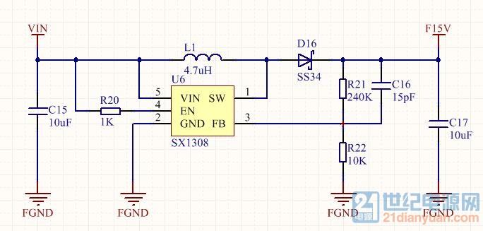
Przetwornica SX1308 Moduł
zasilacza-przetwornicy napięcia DC-DC step up – Moduł
podwyższający napięcie na wyjściu. STEP-UP 2A 2-28V - odpowiednik
LM2577 XL6009
PDF SX1308 POBIERZ (699 KB)
Napięcie wejściowe: 2-24V Napięcie wyjściowe
(regulowane) : 2-28V Maks. prąd wyjściowy: 2A
Częstotliwość pracy
:1.2MHz Wydajność: min. 95%
PDF SS34 POBIERZ (55,9 KB)
Temperatura pracy: -5° ~ +55° Dla wyższych napięć można uzyskać 3A chwilowego. PDF SDB628 POBIERZ (809 KB) Przetwornica ma zabezpieczenie przed przegrzaniem, ale przy dużych prądach wejściowych można zadbać o dobre chłodzenie, np. naklejając radiator od spodu płytki przez podkładkę silikonową, uważając na wystające pady żeby ich nie zewrzeć. |
 |
|
|
 |
Przetwornica DC-DC - MT3608 Przetwornica podnosząca napięcie (step-up) wejściowe z zakresu od 3-25V DC do napięcia 4-28V DC. Napięcie regulowane jest przy pomocy potencjometru. Maksymalne obciążenie to 2A częstotliwość pracy 1,2MHz PDF MT3608 POBIERZ (597 KB) |
|
|
|
 1.2W AUDIO AMPLIFIER |
|
|
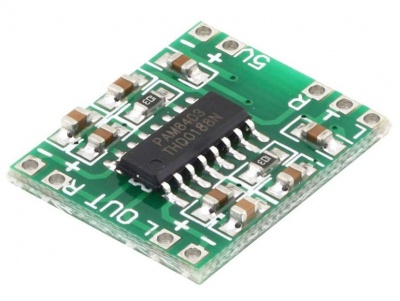 PDF PAM8403 POBIERZ (375 KB) |
 The PAM8403 is a 2x3W, class-D audio amplifier. |
|
|
 The PAM8406 is a 2x5W audio amplifier with an alternative option between Class-D |
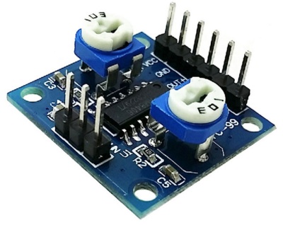 PDF PAM8406 POBIERZ (555 KB) |
|
|
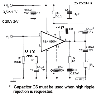
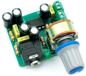 PDF AVT1782 POBIERZ (835 KB) |
 Prosty wzmacniacz słuchawkowy z układem TDA2822 |
|
|
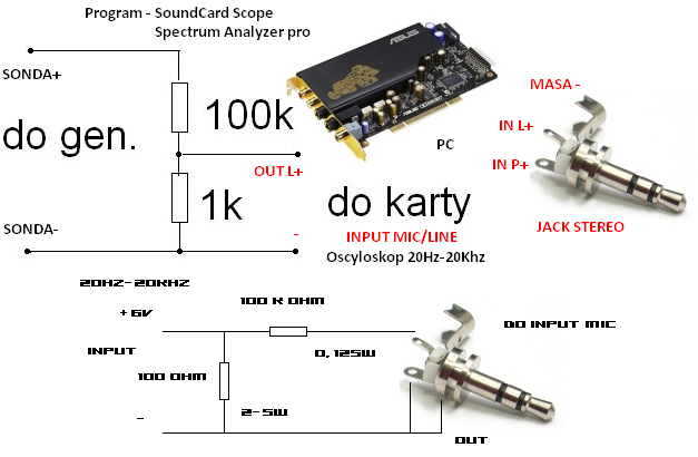 |
Prosty oscyloskop w komputerze PC. Potrzebne
oprogramowanie: Visual Analyzer 2010 NE-XT v2.4 |
|
|
|
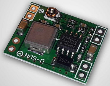
Moduł miniaturowej przetwornicy DC-DC,
step-down (obniżającej napięcie), wykonanej na układzie MP1584.
Przetwornica umożliwia obniżenie napięcia z zakresu 4,5V - 28V do
napięcia 0,8 - 18V, napięcie wejściowe musi być co najmniej 1,5V
wyższe od napięcia wyjściowego. Bez radiatora przetwornica może
pracować z prądem do 1A, przy wyższych prądach należy zamontować
radiator. Napięcie wyjściowe reguluje się za pomocą potencjometru
zamontowanego na płytce przetwornicy. PDF MP1584 POBIERZ (387 KB) |
 |
|
|
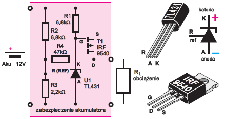 Prąd obciążenia: – bez radiatora 0 do 3A, – z radiatorem do 10A. PDF TL431 POBIERZ (2,46MB) PDF IRF9540 POBIERZ (277KB) |
|
|
|
|
The LM137 and LM337 are adjustable 3-terminal
negative voltage regulators capable of supplying in excess of −1.5A
over an output voltage range of −1.2V to −37V. These LM137 and LM337 regulators are very easy to use in any application and require only 2 external resistors to set the output voltage and 1 output capacitor for frequency compensation. The LM137 and LM337 circuit design has been optimized for excellent regulation and low thermal transients. The LM137 LM337 serve a wide variety of applications including local on-card regulation, programmable-output voltage regulation or precision current regulation and are the ideal complements for LM117 LM317 adjustable positive voltage regulators. Main features of these three terminal voltage regulators are: output voltage adjustable from −1.2V to −37V, 1.5A output current guaranteed, line regulation typically 0.01%/V, load regulation typically 0.3% Output voltage for this configuration can be calculated using this formula: 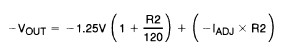 C1 value is around 100uF electrolytic and C2 value is around 1uF solid tantalum.
|
|
|
|
|
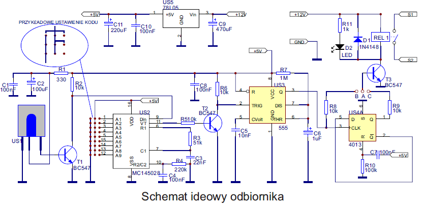
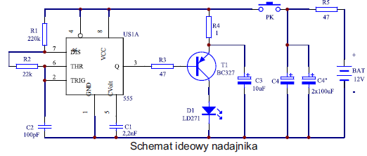
J-216 Zdalne sterowanie kodowane na
podczerwień.
PDF J-216 POBIERZ (1,67 MB) |
|
|
|
|


|
|
Ładowarka akumulatorów PB
POBIERZ J-259 PDF
(1,37 MB)
|
|
|
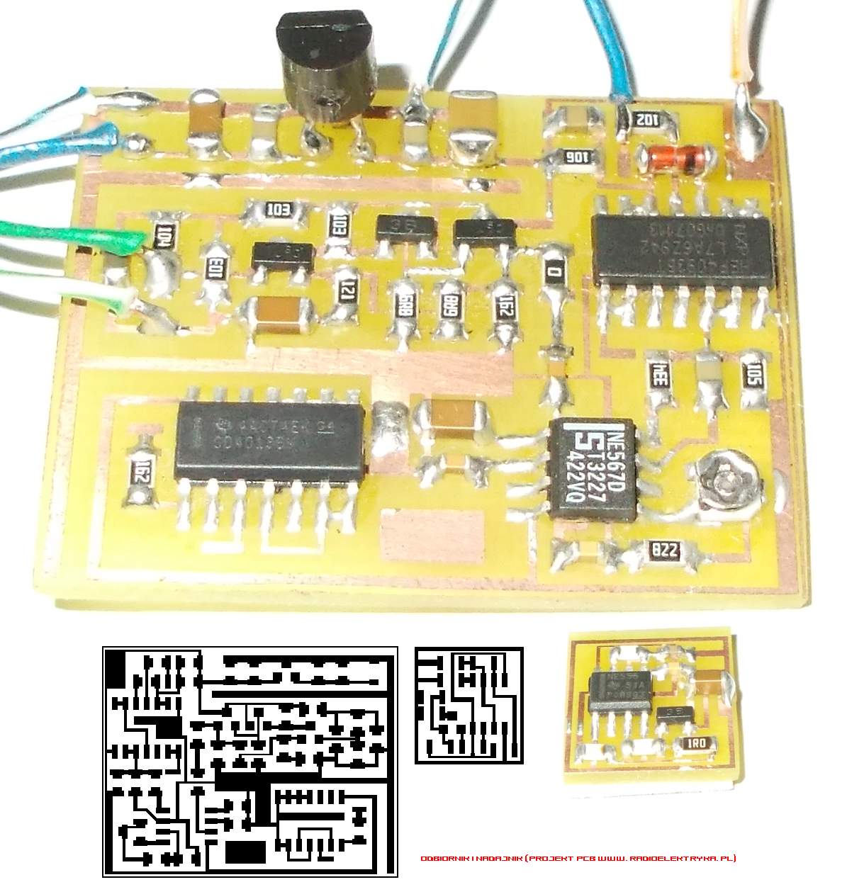
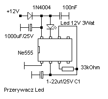
Prosty przerywacz Led (taśma Led 12 Volt). Przy zastosowaniu wartości C 1 4,7-10 uf zmiany częstotliwości błysków można regulować za pomocą napięcia zasilania całego układu w granicach 9-15 Volt. |
|
|
|
|
|
Transmitter stabilizowany rezonatorem kwarcowym. Odporny na dotyk. |
|
|
 |
Woda (tlenek wodoru; nazwa systematyczna IUPAC:
oksydan) – związek chemiczny o wzorze H2O, występujący w warunkach
standardowych w stanie ciekłym. W stanie gazowym wodę określa się
mianem pary wodnej, a w stałym stanie skupienia – lodem. Słowo woda
jako nazwa związku chemicznego może się odnosić do każdego stanu
skupienia. Woda jest bardzo dobrym rozpuszczalnikiem dla substancji polarnych. Większość występującej na Ziemi wody jest „słona” (około 97,38%), tzn. zawiera dużo rozpuszczonych soli, głównie chlorku sodu. W naturalnej wodzie rozpuszczone są gazy atmosferyczne, z których w największym stężeniu znajduje się dwutlenek węgla. Woda naturalna w wielu przypadkach przed zastosowaniem musi zostać uzdatniona. Proces uzdatniania wody dotyczy zarówno wody pitnej, jak i przemysłowej. |
|
|
|
|
|
|
|
|
|
STRONA NR - 1 |
|
|
|
|
