|
Aircraft / Airplane Radio Receiver
Aircraft / Airplane Radio Receiver
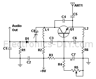
Component List:
R1, R3 - 47K 1/4W Resistor
R2 - 10K 1/4W Resistor
R4 - 4.7K 1/4W Resistor
R5 - 5K Linear Taper Pot
R6 - 2.2K 1/4W Resistor
C1, C2, C3, C6 - 0.001uF Ceramic Disc Capacitor
C4 - 2.2pF Ceramic Disc Capacitor
C5 - 1pF Ceramic Disc Capacitor
C7 - 15uF 15V Electrolytic Capacitor
C8 - 18pF Variable Capacitor
D1 - 1N82 Diode
Q1 - 2N918 NPN Transistor
L1 - See Notes
L2 - 1.8uH Inductor
ANT1 - Approx. 18 Inch Wire Antenna
MISC - PC Board, Wire, Knob For C8 |
 |
|
Technical Specifications:
Voltage Supply: 9-12V
Operating Frequency: 220MHz - 400MHz
Aircraft / Airplane Radio Receiver
The communications between commercial aircraft and the ground can be
interesting, amusing and sometimes even disturbing. However radios
that receive the approximately 220MHz to 400MHz band commonly used
for aircraft (both military and commercial) are not easily found.
And scanners can be complicated, large and expensive. With an easy
to build circuit such as this one, everyone can enjoy listening in
on these conversations.
It's a lot of fun to listen in on airplane / aircraft
communications, and this electronic circuit gives you a feasible
alternative to the very expensive commercial radio scanners that are
available on the market. Awesome for us hobbyists!
This aircraft receiver electronic circuit was first published in the
Think Tank column of the Sept. 1995 issue of Popular Electronics,
and it looks very simple to build, with only about 20 electronic
components.
L1 is made by winding 2 turns of 22 AWG magnet wire on a 5/32 drill
bit. This inductor can be modified to shift the frequency range of
the circuit. The antenna can also be placed at the anode of D1 if
overload is a problem with it connected to the emitter of Q1. R5
adjusts regen and thus sensitivity.
PL
Samoloty / Samolot Radio Receiver
Komunikacja pomiędzy samolotów komercyjnych i ziemi może być
interesujące, zabawne, a czasem nawet niepokojące. Jednak radia,
które otrzymają około 220MHz do 400MHz pasma powszechnie stosowanych
w statkach powietrznych (zarówno wojskowych i komercyjnych), nie są
łatwe do znalezienia. I skanery mogą być skomplikowane, duże i
kosztowne. Z łatwym do zbudowania układu takiego jak ten, każdy może
słuchać w tych rozmowach.
Jest dużo zabawy do słuchania w sprawie łączności samolotu / statku
powietrznego, a ten układ elektroniczny daje realną alternatywę dla
drogich komercyjnych skanerów bardzo radiowych, które są dostępne na
rynku. Niesamowite dla nas hobbystów!
Ten odbiornik samolotu układ elektroniczny został opublikowany po
raz pierwszy w kolumnie think tanku z emisją Popular Electronics
września 1995, i wygląda bardzo prosty w budowie, a tylko około 20
elementów elektronicznych.
L1 jest przez uzwojenie 2 zwoje drutu 22 AWG magnesem na kawałku
5/32 wiertniczej. Ta cewka indukcyjna może być zmodyfikowany tak,
aby przesunąć zakres częstotliwości od obwodu. Antena może być
również umieszczona na anodzie D1 jeśli przeciążenie jest problem z
nim połączony z emitera Q1. R5 dostosowuje regen, a tym samym
czułość. |
